A three-phase model of an autotransformer used in determining GIC flow is shown in Figure 1. Note that the delta tertiary winding (if applicable) is not included in the DSS model since it does not have any physical connection to ground. The common autotransformer neutral (H0/X0) is modeled explicitly.


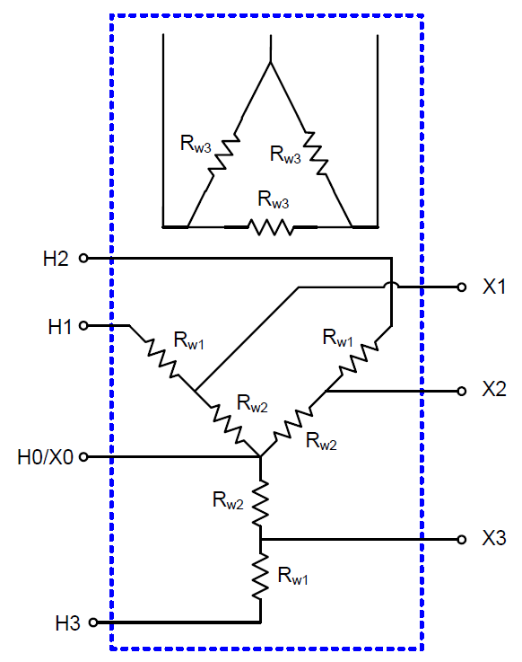
Figure 1 Three-phase Model of a Three-Winding Autotransformer


Rw1 and Rw2 are defined as the dc resistance values of the series and common windings, respectively. Transformer windings are modeled in DSS with resistive branch circuits as shown in Figure 2.


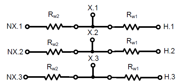
Figure 2. Two-winding and Three-winding Autotransformer model in DSS


The winding terminals designated as NX.1, NX.2, and NX.3 in Figure 48 must be connected together to construct the neutral connection. The bus numbers are arbitrary, but typically the name of the high side bus with the next available terminal number is used to designate the neutral bus. An example OpenDSS script with high voltage bus named ‘Bus1’, low voltage bus named ‘Bus2’, dc winding resistance of 0.1 Ω/phase for the series winding and 0.2 Ω/phase for the common winding is as follows:


New GICTransformer.T1 busH=Bus1.1.2.3 busX=Bus2.1.2.3 busNX=Bus1.4.4.4 R1=0.1 R2=0.2 type=auto


The properties of the GICTransformer model, in order, are:


Basefreq

Inherited Property for all PCElements. Base frequency for specification of reactance value.

busH

Name of bus High-side (H) bus. Node order definitions optional.

busNH

Name of Neutral bus for H, or first, winding. Defaults to all phases connected to H-side bus, node 0, if not specified and transformer type is either GSU or YY. (Shunt Wye Connection to ground reference)For Auto, this is automatically set to the X bus.

busNX

Name of Neutral bus for X, or Second, winding. Defaults to all phases connected to X-side bus, node 0, if not specified. (Shunt Wye Connection to ground reference).

busX

Name of bus Low-side (X) bus. Node order definitions optional.

emergamps

Maximum current. Typically not specified in GIC calculations.

enabled

{Yes|No or True|False} Indicates whether this element is enabled. Default is Yes/True.

phases

Number of phases. Default is 3.

R1

Resistance, each phase, ohms for H winding, (Series winding, if Auto). Default is 0.0001.

R2

Resistance, each phase, ohms for X winding, (Common winding, if Auto). Default is 0.0001.

Type

Type of transformer: {GSU* | Auto | YY}. Default is GSU.

MVA

Optional. MVA Rating assumed Transformer. Default is 100. Used for computing vars due to GIC and winding resistances if kV and MVA ratings are specified.

KVLL1

Optional. kV LL rating for H winding (winding 1). Default is 500. Required if you are going to export vars for power flow analysis or enter winding resistances in percent.

KVLL2

Optional. kV LL rating for X winding (winding 2). Default is 138. Required if you are going to export vars for power flow analysis or enter winding resistances in percent..

%R1

Optional. Percent Resistance, each phase, for H winding (1), (Series winding, if Auto). Default is 0.2. Alternative way to enter R1 value. It is the actual resistances in ohmns that matter. MVA and kV should be specified.

%R2

Optional. Percent Resistance, each phase, for X winding (2), (Common winding, if Auto). Default is 0.2. Alternative way to enter R2 value. It is the actual resistances in ohms that matter. MVA and kV should be specified.

K

Mvar K factor. Default way to convert GIC Amps in H winding (winding 1) to Mvar. Default is 2.2. Commonly-used simple multiplier for estimating Mvar losses for power flow analysis.

Mvar = K * kvLL * GIC per phase / 1000


Mutually exclusive with using the VarCurve property and pu curves.If you specify this (default), VarCurve is ignored.

VarCurve

Optional. XYCurve object name. Curve is expected as TOTAL pu vars vs pu GIC amps/phase. Vars are in pu of the MVA property. No Default value. Required only if you are going to export vars for power flow analysis using curves. See K property.

like

Make like another object, e.g. New GICTransformer.T2 like=T1 ...


The following properties are inherited from the Power Delivery element class, but are ignored for GIC calculations


normamps

Normal rated current. Typically not specified in GIC calculations.

emergamps

Maximum current. Typically not specified in GIC calculations.

pctperm

Percent of failures that become permanent. Typically not specified in GIC calculations.

repair

Hours to repair. Typically not specified in GIC calculations.