The capacitor model is basically implemented as a two-terminal power delivery element. However, if you don't specify a connection for the second bus, it will default to the 0 node (ground reference) of the same bus to which the first terminal is connected. That is, it defaults to a grounded wye (star) shunt capacitor bank.


These connection rules also apply to Vsource, Reactor, and Fault elements.


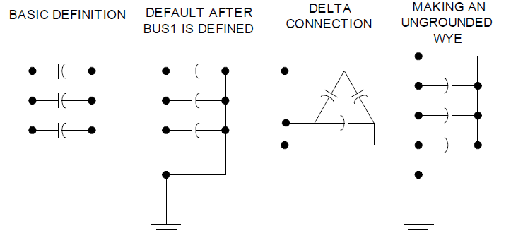
Figure 1: Definition of Capacitor Object


If you specify the connection to be "delta" then the second terminal is eliminated.


If you wish a series capacitor, simply specify a second bus connection.


If you wish an ungrounded wye capacitor, set all the second terminal conductors to an empty node on the first terminal bus, e.g.:


...Bus1=B1 bus2 = B1.4.4.4 ! for a 3-phase capacitor


Of course, any other connection is possibly by explicitly specifying the nodes.


While the Capacitor object is frequently treated as if it were a single capacitor bank, it is actually implemented as a multistep tuned filter bank. Many of the properties can be specified as arrays. See Numsteps property.


If you wish to represent a filter bank, specify either the XL or Harm property. When a Capcontrol object switches a capacitor, it does so by incrementing or decrementing the active step.


Properties, in order, are:


Bus1

Definition for the connection of the first bus. When this is set, Bus2 is set to the same bus name, except with all terminals connected to node 0 (ground reference). Set Bus 2 at some time later if you wish a different connection.

Bus2

Bus connection for second terminal. Must always be specified after Bus1 for series capacitor. Not necessary to specify for delta or grd-wye shunt capacitor. Must be specified to achieve an ungrounded neutral point connection.

Phases

Number of phases. Default is 3.

Kvar

Most common of three ways to define a power capacitor. Rated kvar at rated kV, total of all phases. Each phase is assumed equal. Normamps and Emergamps automatically computed. Default is 600.0 kvar. Total kvar, if one step, or ARRAY of kvar ratings for each step. Evenly divided among phases. See rules for NUMSTEPS.

Kv

Rated kV of the capacitor (not necessarily same as bus rating). For Phases=2 or Phases=3, enter line-to-line (phase-to-phase) rated voltage. For all other numbers of phases, enter actual can rating. (For Delta connection this is always line-to-line rated voltage). Default is 12.47 kV.

Conn

Connection of bank. One of {wye | ln} for wye connected banks or {delta | ll} for delta (line-line) connected banks. Default is wye (or straight-through for series capacitor).

Cmatrix

Alternate method of defining a capacitor bank. Enter nodal capacitance matrix in f. Can be used to define either series or shunt banks. Form should be:

Cmatrix=[c11 | -c21 c22 | -c31 -c32 c33]

All steps are assumed the same if this property is used.

Cuf

Alternate method of defining a capacitor bank. Enter a value or ARRAY of values for C in uf. ARRAY of Capacitance, each phase, for each step, microfarads. See Rules for NumSteps.

R

ARRAY of series resistance in each phase (line), ohms. Default is 0.0

XL

ARRAY of series inductive reactance(s) in each phase (line) for filter, ohms at base frequency. Use this OR "h" property to define filter. Default is 0.0.

Harm

ARRAY of harmonics to which each step is tuned. Zero is interpreted as meaning zero reactance (no filter). Default is zero.

Numsteps

Number of steps in this capacitor bank. Default = 1. Forces reallocation of the capacitance, reactor, and states array. Rules: If this property was previously =1, the value in the kvar property is divided equally among the steps. The kvar property does not need to be reset if that is correct. If the Cuf or Cmatrix property was used previously, all steps are set to the value of the first step. The states property is set to all steps on. All filter steps are initially set to the same harmonic. If this property was previously >1, the arrays are reallocated, but no values are altered. You must SUBSEQUENTLY assign all array properties.

states

ARRAY of integers {1|0} states representing the state of each step (on|off). Defaults to 1 when reallocated (on). Capcontrol will modify this array as it turns steps on or off. At each time step, the States array is recorded by a Monitor object connected to the Capacitor with Mode=6.

Normamps

Normal current rating. Automatically computed if kvar is specified. Otherwise, you need to specify if you wish to use it.

Emergamps

Overload rating. Defaults to 135% of Normamps.

Faultrate

Annual failure rate. Failure events per year. Default is 0.0005.

Pctperm

Percent of faults that are permanent. Default is 100.0.

Basefreq

Base frequency, Hz. Default is 60.0

Like

Name of another Capacitor object on which to base this one.