Circuit Reduction for Version 8.5
OpenDSS Circuit Reduction Updates
The circuit reduction algorithms in OpenDSS have been updated since the end of 2018. Key changes are:
Reduce Shortlines Option
The Reduce Stubs option was replaced with the Reduce ShortLines option. The functionality is similar, but the reduction is performed on a larger set of line objects. The nominal technique is to merge line objects with less positive-sequence impedance than the value specified by the Zmag option with the downline Line object. Zmag may be set on the same command line as a Set ReduceOption command. The bus between the two lines is eliminated.
In most cases, the Load, PVSystem and Storage elements on the eliminated bus are moved to the upline bus of the merged line. If the identified short line is at the end of a branch, the load elements are moved to the downline, or “to”, bus.
If the bus that would be eliminated is marked as a ‘keep’ bus or has either a shunt capacitor or shunt reactor, no merge is performed.
Similarly, if the short line identified has a Control element or is being monitored by another element, no merge is performed. Thus, controls and monitors are preserved.
Reduce Laterals Option
This option was updated from its previous implementation in Version 7. Its primary purpose is to quickly eliminate all 1-phase laterals to achieve a dramatic reduction in node count on circuits where the main planning interest is on the 3-phase sections. If the KeepLoad option is set (with Set Command – true by default), all loads and other shunt elements are moved to the corresponding node on the bus at the head of the lateral. Voltage bases are adjusted, if necessary. In the previous implementation, an equivalent load was created at the head of the lateral to match the kW and kvar of the power flow solution. However, this did not properly represent Load elements with different Loadshapes or the characteristics of PVSystem and Storage elements.
It is possible, and likely, that there could be dozens of Power Conversion (PC) elements on the same node. This is not a conceptual problem for OpenDSS because each element simply contributes its compensation current to the main current array. There is no limit on the number of PC elements and other shunt elements that may be connected to a node. There will be some overhead in the solution algorithm to collect all the individual current contributions. However, this will be offset in many cases of large circuits in which hundreds of 1-phase buses and corresponding nodes are eliminated
and removed from the System Y matrix.
In the future, all single-phase PC elements of the same class might be merged to save computational effort. However, there are complications with this with respect to OpenDSS loadshapes, irradiance shapes, and storage controllers. and it was not attempted in this revision
Controlled and monitored elements are removed or moved in this reduction option, which is the opposite of what happens in the Remove ShortLine option.
Any 1-phase Capacitor or Reactor elements present on the lateral are also moved and their contribution to reactive power preserved. These elements are linear and are completely modeled in the System Y matrix and do not contribute to the main current array.
One downside of this reduction algorithm is that the losses in the single-phase lateral are no longer represented in the analysis. See the example at the end of this document.
Access to Reduction Commands through the COM Interface
A special interface named ReduceCkt was added to the COM interface to make it easier for those driving the OpenDSS from some other tool to execute the circuit reduction algorithms. All the circuit reduction options may be executed and saving the reduced circuit is facilitated. See the description below. Of course, the text command interface may also be used to execute the reduction commands. An Excel VBA example is provided in this document. The spreadsheet is also posted to the OpenDSS Version 8 website:
https://sourceforge.net/p/electricdss/code/HEAD/tree/trunk/Version8/Distrib/Examples/Excel
The Circuit Reduction Process
The Circuit reduction function is executed through EnergyMeter elements in the circuit. An EnergyMeter element is the only place in OpenDSS where the radial circuit tree is built and maintained. Otherwise, all other functions are designed to work equally well whether the circuit is radial or meshed. The circuit tree was incorporated into the Energymeter element very early after the creation of the original DSS program to compute the Energy Exceeding Normal (EEN) and Unserved Energy (UE) values. These values are used to create a risk function for distribution planning and requires knowledge of series overloaded elements. Later, during the EPRI Green Circuits research project, many loss functions were added to the EnergyMeter model that
require radial circuits. The predictive reliability calculation also requires radial circuits and is, therefore, also incorporated into the EnergyMeter element.
Scripting Commands
The basic scripting process for circuit reduction from the text scripting interface or DSS file is:
1. Set ReduceOption = (see table below)
2. Execute the Reduce Command in one of the follow methods:
a. Reduce All (the default; reduces all meter zones using the ReductOption)
i. Or, simply Reduce
b. Reduce EnergyMeterName (reduces the zone of only one meter)
Alternatively, you can execute a specific EnergyMeter reduction function using the Action property of an EnergyMeter element”
• EnergyMeter.MyMeter.Action=Reduce
It is recommended that you execute a Save Circuit command after performing a circuit reduction. Then read the saved reduced circuit back in so that OpenDSS properly reorganizes its circuit element structures. Otherwise, there is a high probability of having control elements and other circuit and general library elements left without proper references. Use the Dir=option on the Save Circuit command. OpenDSS will write a new Master file in this directory and reports the full path name in the Result window and variables.
• Save Circuit Dir=MyDirName
To reload the circuit, copy the contents of the Result window to the clipboard and append to the Compile command.
Circuit Reduction Options
The updated options for the “Set ReduceOption=” command for setting the strategy for reducing feeders are:
Table 1. Circuit Reduction Options in OpenDSS (8.9.5)
|
Option Name |
Description |
|
Default or [null] |
The default reduction strategy is to eliminate all dangling end buses and buses without load. |
|
Shortlines [Zmag=nnn] |
Merges short line sections having impedance less than Zmag, expressed in ohms. The default value of Zmag is 0.01 ohms. Power conversion elements on buses eliminated by the merging are generally moved to the downline (“To” side) bus unless it is an end node. Buses containing Capacitor or Reactor elements are not eliminated. |
|
MergeParallel |
Merges Line objects that are in parallel. |
|
BreakLoops |
Disables one of the Line objects at the head of a loop to force the circuit to be radial. |
|
Switches |
Merges Line objects in which the IsSwitch property is true with the downline Line object. Eliminates dangling switches. Does not check if a SwtControl object is connected to a Line. The purpose is to eliminate very short Line sections quickly. The ShortLines option can also accomplish this (most Switch lines will have an impedance of 1 millohm). |
|
Ends |
Eliminates dangling ends only. |
|
Laterals [Keepload=Yes*/No] |
Removes all 1-phase laterals. By default, lumps Load, PVSystem, and Storage elements at the head of the lateral where it branches from the main feeder. Keeplist is ignored for this option; laterals are complete removed. |
Marking buses with "Keeplist" will prevent their elimination.
Remove Command
Syntax: Remove {ElementName=} [KeepLoad=Y*/N] [EditString="..."]
Removes, by disabling, all branches downline from the PDelement named in the "ElementName" property. Circuit must have at least one Energymeter object at the head of the feeder and the branch must be part of the circuit tree that belongs to the Energymeter object (the Energymeter object’s zone). The zone is instantiated with the Energymeter is created on the first solution. It is updated for each subsequent solution.
If KeepLoad=Yes (which is the default) a new Load element is defined at the bus on the source side (“from” side) of the PDElement object. Its kW and kvar set to the present power flow solution for the “From”, or upstream, terminal of the first element eliminated. The new Load object voltage rating is set to the voltage base of the bus or the actual voltage if the voltage base is not defined.
The EditString is applied to each new Load element defined.
If KeepLoad=N, all downline elements are disabled.
Examples:
Remove Line.Lin3021
Remove Line.L22 Editstring="Daily=Dailycurve Duty=SolarShape”
Remove Line.L333 KeepLoad=No
ReduceCkt Interface
In Version 8.5.9, the circuit reduction functions were made available through the COM interface with the addition of the ReductCkt interface. Figure 1 shows a screen capture of the interface from the Excel VBA Object Browser. There is a separate method (function) beginning with the “Do…” verb for each of the circuit reduction options (see next section). There are also properties in the interface to support the circuit reduction process.

Figure 1. Listing of Methods and Properities in ReduceCkt COM Interface (from
Microsoft Excel)
Table 2. ReduceCkt Interface Methods and Properties
|
Property/Method Name |
Description |
|
Do1phLaterals |
Removes all 1-phase laterals in the active EnergyMeter’s zone. Loads and other shunt elements are moved to the parent 3-phase bus. |
|
DoBranchRemove |
Remove an entire branch downline from designated starting element. Specify StartPDElement, KeepLoad, and EditString before executing. |
|
DoDangling |
Remove dangling end branches with nothing connected |
|
DoDefault |
Executes the default circuit reduction, which eliminates all dangling end buses and buses without load. |
|
DoLoopBreak |
Disables one of the Line objects at the head of a loop to force the circuit to be radial. |
|
DoParallelLines |
Merges Line object that are in parallel |
|
DoShortlines |
Removes Line objects with less impedance than specified by the Zmag property. Specify the Zmag property before executing. |
|
DoSwitches |
Merges Line objects in which the IsSwitch property is true with the downline Line object. |
|
EditString |
[String] String containing the OpenDSS command appended to the BranchRemove option when a new load is defined to represent the load on the removed branch. |
|
EnergyMeter |
[String] Name of EnergyMeter object for circuit reduction |
|
KeepLoad |
[Boolean T/F] Set flag to keep load for reduce functions that remove branches. |
|
SaveCircuit(dirname) |
Execute the Save Circuit command from the COM interface. Saves the reduced circuit in a directory with the specified name. The full path name of the Master.DSS file is return in the DSSText.Result property. |
|
StartPDElement |
[String] Full name of the first PDelement for the BranchRemove command. |
|
Zmag |
[Double] Value of impedance value associated with the DoShortLines method. Lines with less impedance will be merged out of the circuit, eliminating one or more buses. |
Examples
Circuit Reduction Script (for OpenDSS.exe)
CD C:\Users\prdu001\OpenDSS\Distrib\EPRITestCircuits\ckt5\
// Original EPRI Ckt5 model
Compile [Master_ckt5.dss]
Solve
Plot Circuit Power Max=1500 dots=y labels=n subs=y C1=Blue 1phlinestyle=3
Plot Profile
// 1st Reduction: Reduce out all 1-phase laterals
Set ReduceOption = Laterals ! reduce 1-phase laterals
Reduce
Save Circuit Dir=Test1
// Reload reduced circuit
Compile "C:\Users\prdu001\OpenDSS\Distrib\EPRITestCircuits\ckt5\Test1\Master.DSS"
CalcVoltagebases
Solve
Interpolate
Plot Circuit Power Max=1500 dots=y labels=n subs=y C1=Blue 1phlinestyle=3
Plot Profile
// 2nd Reduction: Eliminate lines shorter than 1 ohm
Set Zmag=1.0 ! ohms
Set ReduceOption = Shortlines
Reduce
Save Circuit Dir=Test2
// Reload reduced circuit
Compile "C:\Users\prdu001\OpenDSS\Distrib\EPRITestCircuits\ckt5\Test2\Master.DSS"
CalcVoltagebases
Solve
Interpolate
Plot Circuit Power Max=1500 dots=y labels=n subs=y C1=Blue 1phlinestyle=3
Plot Profile
Results
In this section we show the results of the circuit reduction of EPRI Ckt5 graphically. Numerical results are given after the COM interface example that follows.

Figure 2. Original Circuit
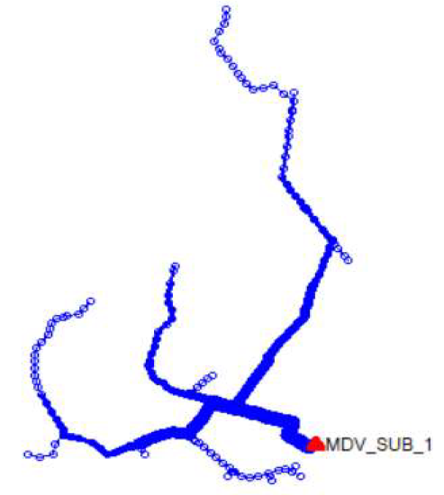
Figure 3. After Removing 1-phase laterals
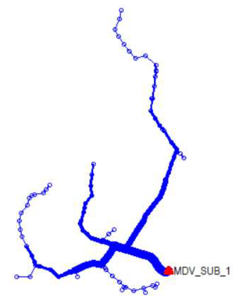
Figure 4. After 2nd Reduction
Original

1-Phase Laterals Removed
Short Lines Merged
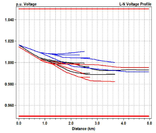
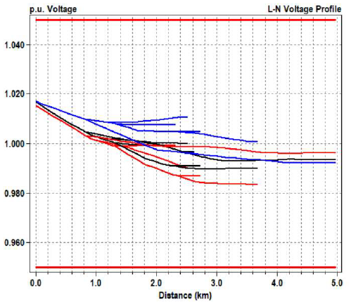
Figure 5. Voltage Profiles for the Three levels of Circuit Reduction.
Circuit Reduction Using the COM Interface (Excel VBA)
The VBA subroutine (also called a macro) below executes the same script as described above. It also prints out some of the results from each step of the reduction.
Public Sub TestReduce()
'
' VBA subroutine to illustrate using the ReduceCkt COM interface
'
Dim DSSReduce As OpenDSSEngine.ReduceCkt
Dim CompileStr As String
Dim V As Variant
' The ReduceCkt interface is connected through the Circuit interface
' The DSSCircuit variable points to the Circuit interface
Set DSSReduce = DSSCircuit.ReduceCkt
' Connect DSSReduce variable with the interface
DSSText.Command = "Compile
C:\Users\prdu001\OpenDSS\Distrib\EPRITestCircuits\ckt5\Run_ckt5.dss"
DSSSolution.Solve
With DSSCircuit
Debug.Print "No. Buses Before Reduction ", .NumBuses
Debug.Print "No. Nodes Before Reduction ", .NumNodes
Debug.Print "Total power (kW, kvar) ", .TotalPower(0), .TotalPower(1)
Debug.Print "Losses (kW, kvar) ", .Losses(0) * 0.001, .Losses(1) * 0.001
End With
DSSText.Command = "Plot Circuit Power Max=1500 dots=y labels=n subs=y C1=Blue
1phlinestyle=3" ' Default Circuit plot (power)
DSSText.Command = "Plot Profile" ' Voltage profile
' First Reduction -- get rid of all 1-ph laterals
' This moves Load, PVSystem, Storage, Capacitor (shunt), and Reactor (shunt)
‘ elements on the laterals to the 3-phase buses at the head of the laterals
DSSReduce.Do1phLaterals
' After a reduction, save the reduced circuit. Otherwise, key values might be lost
DSSReduce.SaveCircuit "ComTest1"
CompileStr = DSSText.Result ' Get name of reduced Master file
DSSText.Command = "Compile " + CompileStr ' Read reduced circuit back in
Debug.Print CompileStr ' Print name of compile file for verification
' The reduction saves the voltage bases, but does not have a CalcVoltageBases
‘ command in the Master file.
‘ So execute it separately to set all the voltage bases
DSSText.Command = "CalcV"
DSSCircuit.Solution.Solve ' solve the reduced circuit
With DSSCircuit
Debug.Print "Buses After Reduction ", DSSCircuit.
Debug.Print "No. Nodes After Reduction ", .NumNodes
Debug.Print "Total power (kW, kvar) ", .TotalPower(0), .TotalPower(1)
Debug.Print "Losses (kW, kvar) ", .Losses(0) * 0.001, .Losses(1) * 0.001
End With
DSSText.Command = "Interpolate"
DSSText.Command = "Plot Circuit Power Max=1500 dots=y labels=n subs=y C1=Blue
1phlinestyle=3" ' Default Circuit plot (power)
DSSText.Command = "Plot Profile" ' Voltage profile
'*************************************************************************************
' Second Reduction -- Short Lines
'*************************************************************************************
' This reduction takes the remaining lines and
‘ merges out lines shorter than 1.0 ohms
DSSReduce.Zmag = 1# ' Set the Zmag value
DSSReduce.DoShortLines
DSSReduce.SaveCircuit "ComTest2" ' Save the circuit after reduction
CompileStr = DSSText.Result ' get name of reduced master file
Debug.Print CompileStr
' Read it back in
DSSText.Command = "Compile " + CompileStr
DSSText.Command = "CalcV" ' set the voltage bases
DSSCircuit.Solution.Solve
DSSText.Command = "Show Power kVA elem"
With DSSCircuit
Debug.Print "No. Buses After Reduction ", .NumBuses
Debug.Print "No. Nodes After Reduction ", .NumNodes
Debug.Print "Total power (kW, kvar) ", .TotalPower(0), .TotalPower(1)
Debug.Print "Losses (kW, kvar) ", .Losses(0) * 0.001, .Losses(1) * 0.001
End With
DSSText.Command = "Interpolate" ' fill in missing bus coordinates
DSSText.Command = "Plot Circuit Power Max=1500 dots=y labels=n subs=y C1=Blue
1phlinestyle=3"
DSSText.Command = "Plot Profile"
Output of Excel Circuit Reduction Example
Case 1 ( EPRI Ckt5 model)
No. Buses Before Reduction 2998
No. Nodes Before Reduction 3437
Total power (kW, kvar) -7281.32785831483 -3584.31819736872
Losses (kW, kvar) 266.02500598923 918.768306322668
Case 2 Remove 1-phase Laterals
No. Buses After Reduction 229
No. Nodes After Reduction 668
Total power (kW, kvar) -7237.20109540373 -3537.35138898462
Losses (kW, kvar) 121.214748918846 728.803882238189
Case 3 Merge Short Lines Less than 1 ohm
No. Buses After Reduction 127
No. Nodes After Reduction 368
Total power (kW, kvar) -7237.32110644758 -3537.63462528838
Losses (kW, kvar) 120.129009457863 727.266472370997
Notes:
• The new reduction strategies do a better job of retaining the total powers than the previous version
• Removing the 1-phase laterals removes 140 kW of losses from the circuit model. 100 kW is due to removing the 1-phase load transformers and about 40 kW in line losses.
Reduced Circuit Model Performance
The timing was determine for an 8760-hr yearly simulation for each of the three circuits models. These timings include demand interval metering, which adds about 2 s to the full circuit solution.
OpenDSS8.5.9.1 Dell Precision 5510 (1 actor)
1. Full circuit (Ckt5)
Devices = 4415
Buses = 2998
Nodes = 3437
Time = 50.18 s (5.77283 ms/step)
2. Remove 1-phase laterals
Devices = 1632
Buses = 229
Nodes = 668
Time = 12.90 s (1.4726 ms/step)
3. Reduce ShortLines less than 1 ohm
Devices = 1529
Buses = 127
Nodes = 368
Time = 10.69 s (1.2203 ms/step)