Computing Elements Currents in OpenDSS
Given some recent issues with very short lines or other elements with very tiny impedances, it is worthwhile to go over how the OpenDSS computes currents in circuit elements.
The OpenDSS uses an admittance formulation of the circuit. As illustrated below, the system of equations that is solved includes the Y matrix formed from the impedances of elements in the network, the node voltage with respect to ground (the zero voltage reference), and the “injection” currents.
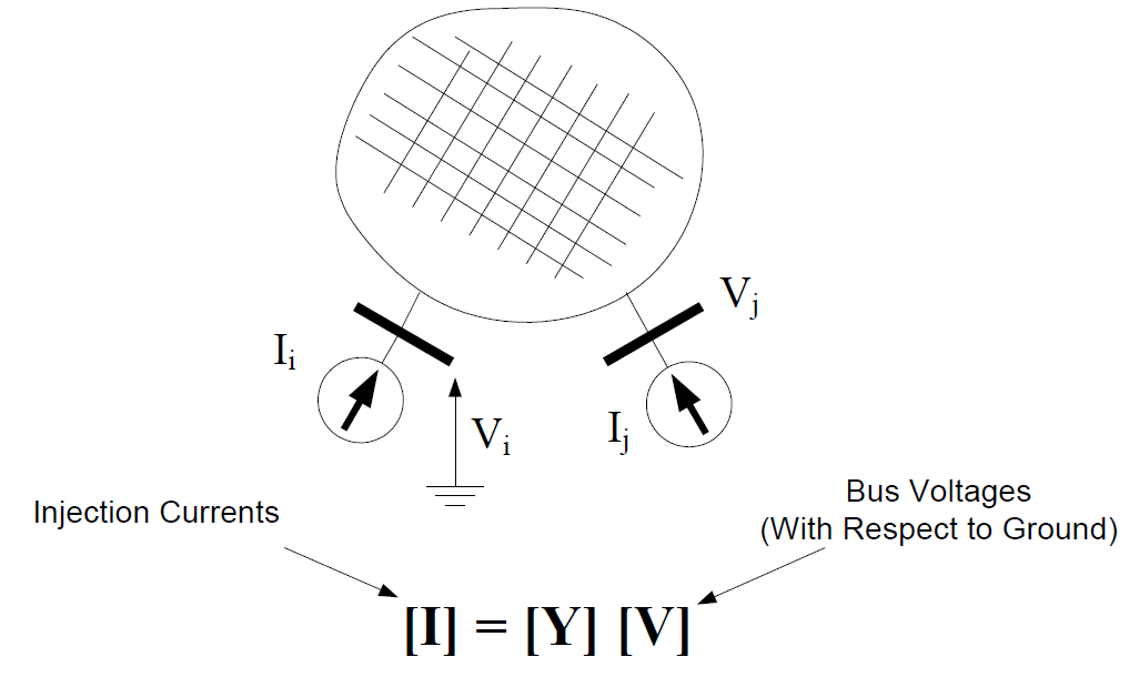
The injection currents are currents being injected into the nodes from outside the network represented in the Y matrix. These are currents from voltage sources and current sources as well as “compensation currents” from nonlinear load or generator models. These are NOT necessarily the currents in the terminals of the circuit elements.
Thus, the OpenDSS solves only for the node voltages. To obtain the currents, the program goes back to each element and “asks” it what its currents are. The DSS executive only keeps track of the node voltages. The process is illustrated below using a simple 3-phase inductive power delivery branch that is represented entirely by its Yprim matrix.
The circuit element knows where to find its node voltages in the main solution voltage array. (For programmers: This is the index in the NodeRef array that is part of each circuit element.) The terminal currents are computed by constructing a vector (array) of the complex node voltages and then multiplying by Yprim.

Note that the order of Yprim is 6x6 in this case. There are 6 nodes (3 phases at each end).
A problem arises when users specify a very tiny impedance to represent a bus bar or switch or a jumper between two buses. The DSS is generally pretty tolerant of this because it uses double precision math throughout. However, in some recent cases imported data has had line sections with a length of, for example, 1E-9 or sometimes, zero. DSS converts the latter to a small impedance. The root of the problem is that the voltages may not converged to sufficient accuracy to obtain accurate currents. With a small impedance, the voltages from one end to the other have only tiny differences which then get multiplied by a large admittance. The result is usually a very large current that is not consistent with other circuit elements connected to the same bus.
The voltage solution is generally correct; it is the reported currents and powers that can be significantly off. Energymeters that are connected to these elements can have erroneous readings.
For primary (MV) circuits, there is seldom a need to represent an impedance less than 0.001 ohms. In fact, fuses throughout the system will often have more resistance than this and it can be difficult at times to make a connection with less resistance. On LV circuits, it may be necessary to allow for a smaller impedance, such as 0.0001 ohms to get an order of magnitude below impedances of transformers if you have the need to represent small jumpers, etc.
Recommendations: Avoid modeling tiny impedances where practical. If used, do not connect energymeters to them. Be on the lookout for any bizarre currents or cases where the reported zone losses (kW and kvar) do not add up to total values.
There have been reports that the EXE version computes to better precision than the COM DLL version of OpenDSS. The reason for this is not known and is under investigation.