Control Actions
The control actions are the actions performed by the controllers deployed across the power system to force the power system variables within a band specified by the power system operator. These controls comprehend generators, regulators, capacitor controls, smart inverters, and other control devices. The control actions depend on the latest solution obtained to determine if a control action needs to happen in the present simulation step.
If control actions need to be applied, they take place and then a new solution is calculated including the modifications triggered by the control actions, which can modify the Y Bus admittance matrix or the injected currents vector, depending on the controller type.
This loop repeats until no new control actions are required or the maximum number of control iterations is reached, which in that case will cancel the simulation and report the issue. Reaching the maximum number of control iterations signals an oscillatory behavior in the controls that requires user intervention for better setup or to coordinate the controllers.
When the solution is found successfully, meaning that there are no more control actions pending in the simulation step and the maximum number of solution/control iterations was not reached, the next step is to sample all the monitors, energy meters, and other sampling devices that register the electrical values obtained for the user-specified elements within the model.
This is the last step in the solution algorithm for the present simulation step, enabling the simulator to continue the simulation for the next time interval. This algorithm is generalized in the diagram shown in Figure 1.
Other processes around the solution algorithm include debugging logs to facilitate the controls and model tuning when something goes wrong. These are user-configurable options. The algorithm in Figure 1 represents the solution implemented in OpenDSS for QSTS simulations. Other solution modes, such as harmonics, use a similar structure with slight modifications.
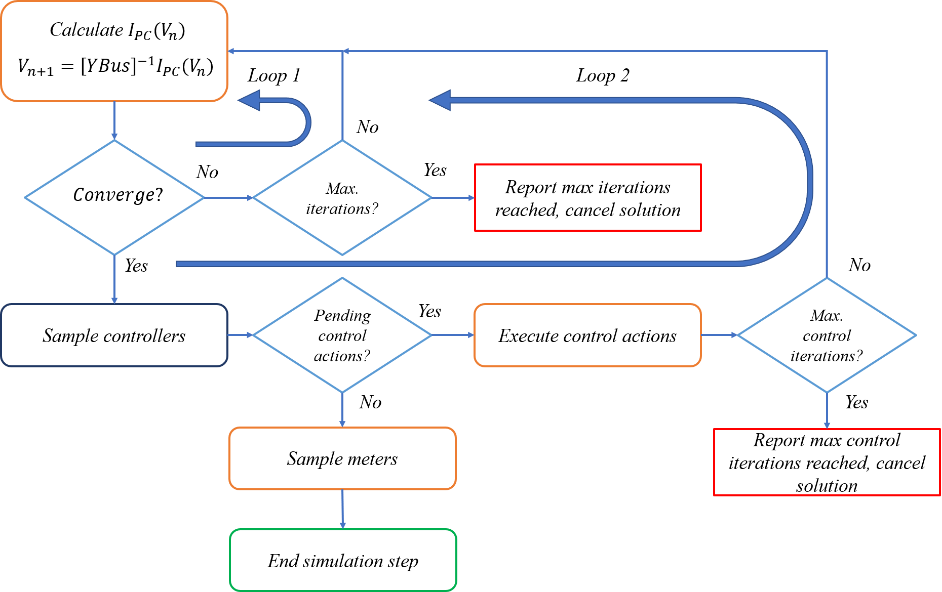
Figure 26. Generalized solution algorithm in OpenDSS
In Figure 1, the solution algorithm contains two main loops and three processes: the solution and control loops and the solution, control actions, and meter sampling processes. The loops represent the parts of the algorithm adding to the computational time required to find a solution. In this case, these loops comprehend two out of three processes of the solution algorithm that may need multiple iterations to complete.
The number of solution and control iterations depends on the power system model features. The maximum number of iterations is user configurable, providing flexibility for solving models with different difficulty levels. The difficulty level is determined by the circuit model’s topology and the type of elements deployed in the model, such as load models, generators, energy storage (ES), PV solar panels, and other technologies that can be connected to the model.
Control actions can also be time consuming in the simulation step. As mentioned above, control actions may require the recalculation of parts of the Y Bus matrix, adding an extra overhead that can be significant in respect to previous processes if a substantial number of controllers require similar control actions. Other controllers do not modify the Y Bus matrix. Instead, they are modeled as current injection devices that modify the power system response by injecting currents at the controlled element’s connection point.