Generator Step-up Banks
A common transformer connection in large networked power systems is the grounded-wye delta connected generator step-up transformer (GSU). A three-phase model of a GSU used in GIC calculations is shown in Figure 1.
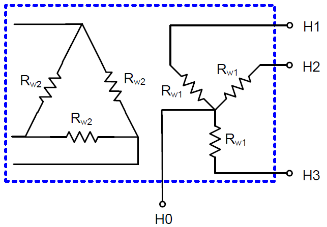
Figure 1. Three-phase Model of a Generator Step-Up Transformer
Note that the delta winding does not have any connection to the external network since it is not physically connected to ground and is open to the zero sequence. Thus, it is not included in the OpenDSS model. The HO terminal refers to the neutral point, and is modeled explicitly. Rw1 and Rw2 are defined as the dc winding resistance values of the high voltage or extra-high voltage and medium voltage windings, respectively.
Transformer windings are modeled with resistive branch circuits as shown in Figure 44.
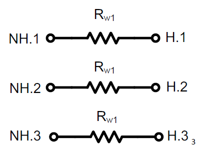
Figure 2. GSU Model in OpenDSS
The winding terminals designated as NH.1, NH.2, and NH.3 in Fig. 2 must be connected together to construct the wye winding. The bus number is arbitrary, but typically the name of the high side bus is used with the next available terminal number. An example OpenDSS script with high voltage bus named ‘Bus1’ and dc winding resistance of 0.1 Ω/phase is as follows:
New GICTransformer.T1 busH=Bus1.1.2.3 busNH=Bus1.4.4.4 R1=0.1 type=GSU
To illustrate the previous comment of utilizing the next available terminal value for the neutral bus, two identical GSUs in parallel can be described by the following:
New GICTransformer.T1 busH=Bus1.1.2.3 busNH=Bus1.4.4.4 R1=0.1 type=GSU
New GICTransformer.T2 busH=Bus1.1.2.3 busNH=Bus1.5.5.5 R1=0.1 type=GSU
Naming the neutral buses in this manner allows for the creation of individual neutral buses for each GSU which is necessary when modeling GIC blocking devices.