LineCode
LineCode objects are general library objects that contain impedance characteristics for lines and cables. The term "line code" is an old distribution system analysis program term that simply refers to a code that was made up by programmers to describe the impedances of a line construction. In most distribution analysis programs, one can describe a line by its LineCode and its length. LineCode objects were defined in a separate file. This collection of objects emulates the old linecode files, except that the concept here is a little more powerful.
Ultimately, the impedance of a line is described by its series impedance matrix and nodal capacitive admittance matrix. These matrices may be specified directly or they can be generated by specifying the symmetrical component data. Note that the impedances of lines may be specified directly in the Line object definition and one does not need to use a LineCode object, although the linecode will be more convenient most of the time and would be easier to read. There may be hundreds of Line objects, but only a few different kinds of line constructions.
A LineCode object definition can also perform a Kron reduction, reducing out the last conductor in the impedance matrices, which would then be assumed to be a neutral conductor, with zero volts at each end (i.e., grounded). This applies only if the impedance is specified as a matrix. If the impedance is defined using symmetrical components, this function does not apply because symmetrical component values already assume the reduction.
This assumes the impedance matrix is constructed as follows, which is typical for power system analysis:
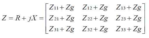
Where, using the 1st term of Carson’s formulation,
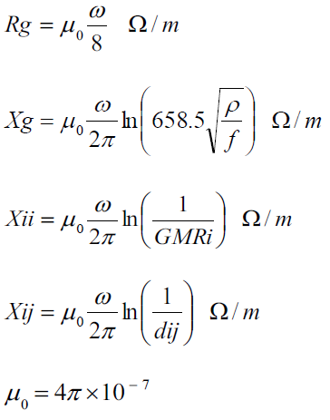
(All dimensional values in meters.)
By specifying the values of Rg, Xg, and rho properties used to compute the impedances supplied, OpenDSS will take the base-frequency impedance matrix values and adjust the earth return component for frequency. Skin effect in the conductors is not modified. To represent skin effect, you have to use the LineGeometry class and let OpenDSS compute the impedance matrices. Or you can insert a frequency-dependent Reactor model in series with the line to accound for the variation of impedance with frequency.
The LineCode properties, in order, are: (not case sensitive)
Nphases= Number of phases. Default = 3.
R1 = Positive-Sequence resistance, ohms per unit length.
X1 = Positive-Sequence reactance, ohms per unit length.
R0 = Zero-Sequence resistance, ohms per unit length.
X0 = Zero-Sequence reactance, ohms per unit length.
C1= Positive-Sequence capacitance, nanofarads per unit length.
C0= Zero-Sequence capacitance, nanofarads per unit length.
Units= {mi | km | kft | m | ft | in | cm} Length units. If not specified, it is assumed that the units correspond to the length being used in the Line models.
If any of the Symmetrical Component data is specified, the impedance matrices are determined from that data. You may also enter the matrices directly using the following three parameters. The order of matrices expected is the number of phases. The matrices may be entered in lower triangle form or full matrix. The result is always symmetrical. Matrices are specified by the syntax shown below. The "|" separates rows. Extraneous numbers on each row are ignored.
Rmatrix="11 | 21 22 | 31 32 33"
Rmatrix= Series resistance matrix, ohms per unit length.
Xmatrix= Series reactance matrix, ohms per unit length.
Cmatrix= Shunt nodal capacitance matrix, nanofarads per unit length.
BaseFreq= Base Frequency at which the impedance values are specified. Default = 60.0 Hz.
Normamps= Normal ampacity, amps.
Emergamps= Emergency ampacity, amps.
Faultrate= Number of faults per year per unit length. This is the default for this general line construction.
Pctperm= Percent of the fault that become permanent (requiring a line crew to repair and a sustained interruption).
Kron= Y/N. Default=N. Perform Kron reduction on the impedance matrix after it is formed, reducing order by 1. Do this only on initial definition after matrices are defined. Ignored for symmetrical components.
Rg= Carson earth return resistance per unit length used to compute impedance values at base frequency. See description above. For making better adjustments of line impedance values for frequency for harmonics studies. Default= 0.01805 ohms per 1000 ft at 60 Hz. If you do not wish to adjust the earth return impedance for frequency, set both Rg and Xg to zero. Generally avoid Kron reduction if you will be solving at frequencies other than the base frequency and wish to adjust the earth return impedance.
Xg= Carson earth return reactance per unit length used to compute impedance values at base frequency. See description above. For making better adjustments of line impedance values for frequency for harmonics studies. Default= 0.155081 ohms per 1000 ft at 60 Hz. If you do not wish to adjust the earth return impedance for frequency, set both Rg and Xg to zero. Generally avoid Kron reduction if you will be solving at frequencies other than the base frequency and wish to adjust the earth return impedance.
Rho= Earth resistivity used to compute earth correction factor. Default=100 meter ohms.
Neutral = Designates which conductor is the "neutral" conductor that will be eliminated by Kron reduction. Default is the last conductor (nphases value). After Kron reduction this property is set to 0. Subsequent issuing of Kron=Yes will not do anything until this property is set to a legitimate value. Applies only to LineCodes defined by R, X, and C matrix.
B1, B0 = Alternate way to specify C1 and C0. Micro-siemens per unit length.
Seasons= Defines the number of ratings to be defined for the wire, to be used only when defining seasonal ratings using the "Ratings" property.
Ratings= An array of ratings to be used when the seasonal ratings flag is True. It can be used to insert multiple ratings to change during a QSTS simulation to evaluate different ratings in lines.
Like= Name of an existing LineCode object to build this like.