Model Equivalents
Making Source Equivalents of Large Networks for Power Flow Analysis
For the DSS, we are generally interested in modeling only a few of the buses of the transmission system or subtransmission system surrounding our distribution planning area. This can be as few as maybe 5 or 6 up to a few hundred. The transmission system is generally modeled in PSS/E, PSLF, or a similar program with 15000 or more buses. This is a bit unwieldy for the intensive types of calculations we are doing, so we need to make equivalents for power flow purposes. The DSS can do traditional power flows after a fashion, but it prefers to work with one largecapacity voltage source (swing bus) and then other smaller sources modeled as generators or whatever. The first thing you must do is pick one of the buses to be the infinite bus. This must be done carefully so that there won't be wide voltage excursions as the load is varied. Usually, it is best to pick the largest bus near the planning area, or, at least, the one that is delivering the most power to the area. There are three basic approaches I have tried: 1. A shortcircuit equivalent 2. Power injection equivalent 3. Phase shifting equivalent.
Short Circuit Equivalent
This is perhaps the simplest. You would remove the circuit of interest from PSS/E or PSLF and make s short circuit equivalent of the remaining circuit. The short circuit equivalent naturally assumes it is the equivalent to the infinite bus, so you simply have to connect the equivalent to a big VSOURCE object in the DSS. The downside is that it's difficult to represent the phase shift that is created across the region by the flow of power. The short circuit equivalent frequently does not properly include the effects of load. You can accomplish that by adding some external loading to the short circuit equivalent (see PhaseShifting Equivalent, below).
Power Injection Equivalent
In this method, you pick the biggest bus as the swing bus. Everywhere else you cut the transmission circuit, you install a generator or a negative load representing the flow being injected into the network at that point. You assign a daily load variation loadshape to those injection sources so that they go up and down with the area load. This implicitly assumes that the EMS will keep the load flow in approximately the same proportion as the peak load case. This approach is acceptable in many cases, but not always as flexible as I would like. For example, what do you do if you add a major load to an area? One strategy is to back up a couple of buses in each direction so that the new power addition is small relative to the amount of power in your expanded planning area. But then the size of the problem increases.
PhaseShifting Equivalent
When you have a case such as the LBI planning area which has two major sources of power, you would pick one as the inifinite bus. The issue then is how to represent the rest of the transmission system in a simple manner so that you can get the proper phase shift between the two buses and the proper split in the power delivery. One method would be to simply insert a phase shifting transformer between the two buses. If you are making a full 3phase equivalent in the DSS, you simple construct a transformer and connect the windings to achieve the needed phase shift. If you are using a single-phase, positive-sequence equivalent, you can't do this at present. Maybe one of these days we will have this capability in the DSS, but right now we can handle only symmetrical matrices. A phase-shifter requires a non-symmetrical matrix (if you want an interesting academic excersize, derive the admittance matrix for a phase shifter equivalent). Another issue is that the phase shift does not stay constant with loading. At lighter loads, the voltages on both ends will tend to come closer together in phase. The phase angle change is a natural consequence of the power flowing through the lines and transformers. Thus, I generally prefer to model the equivalent as shown in the figure below.
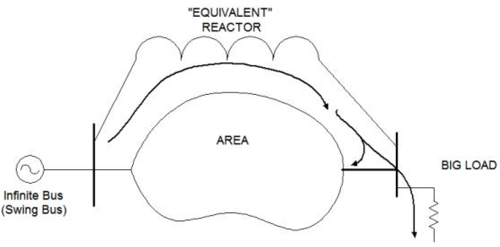
A high capacity "equivalent" reactance is placed around the area. This reactance should yield at least as much fault current at the second bus as would normally appear there. The DSS model would probably work even better if the reactor were somewhat more stiff than the actual system. A big load is hung on the second bus. Generally, this is mostly resistive. It is the power flowing through the reactance to this load that provides the necessary phase shift. Assign a typical load shape to this load and the relative phase angles of the two buses will vary with load. If the buses are two different voltage levels, use a transformer. If the system operator adjusts capacitors or transformer taps to maintain the voltage at the load bus, it would be better to make the equivalent reactance much smaller than actual and use a larger load. This will hold the voltage relatively close to a target value. Alternatively, use a regulating transformer to make the connection. Be aware that if you make the bus too weak, the transformer taps will try to change a lot and will probably mess up your solution convergence.
Procedure
1. Choose a reactance that gives you plenty of short circuit strength.
2. Add it to the model of the planning area.
3. Start the DSS, compile the circuit.
4. Jack up the load, solving after each change, until you achieve the desired phase shift.
5. If the voltage sags too low, reduce the reactance value.
This method can be extended to areas with more than two major sources of power. It just takes a little longer to calibrate. I did this for the Tri-valley area around San Francisco Bay, which has large buses at Tesla, Newark, and Pittsburg (2 buses). I got by using only two reactors: One between the two big buses near Pittsburg and one from Pittsburgh to Tesla. Most of the lines to Newark were already in the planning area and accounted for most of the phase shift after I included the load at Newark. It took about one day to get the equivalent functional.