Voltage source. A Vsource object is a two-terminal, multi-phase Thevenin (short circuit) equivalent. That is, it is a voltage source behind an impedance. The data are specified as it would commonly be for a power system source equivalent: Line-line voltage (kV) and short circuit MVA.


The most common way to use a voltage source object is with the first terminal connected to the bus of interest with the second terminal connected to ground (the voltage reference). In this usage, the connection of the second terminal may be omitted. The second terminal connection defaults to BusName.0.0.0 for a 3-phase source connected to BusName. In 2009, the voltage source was changed from a single-terminal device to a two-terminal device. This allows for the connection of a voltage source between two buses, which is convenient for some types of studies.

The main purpose of a voltage source – also known as Slack Bus – in distribution system modeling is to represent any linear system seen from a bus in the electrical system, typically as a voltage source behind an impedance. Practically speaking, it can represent, for example, the bulk system as seen from a primary substation when modeling a primary substation with its supplied feeders. It can also represent both a primary substation system and the bulk system when modeling one or more feeders without detailed representation of the primary substation.

This concept can be better understood through Figure 1, which represents a fictitious system constituted by two subsystems, S1 e S2, connected to each other through node A. Suppose, for example, that it is of interest to study system S2 only. In this case, supposing that system S1 is linear, the voltage source element can be utilized to represent S1 system entirely, as depicted in Figure 2.


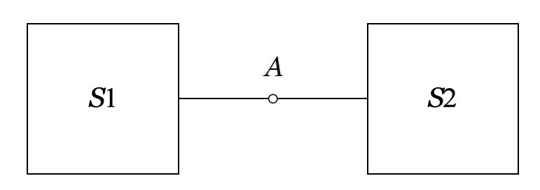
Figure 1: Fictitious Power System


Figure 2: Thevenin Equivalent of System A


Note: Every circuit model in OpenDSS must contain at least one voltage source element. Only the first of these elements (and only the first!) must be specified with type “Circuit” (e.g., New Circuit.MyVoltageSource) while other elements must be specified with type “Vsource”. The “Circuit” element is utilized for initialization of the circuit topology and other internal initialization within OpenDSS, and it can be seen as the “main” voltage source of the circuit model. Voltage source is utilized throughout this document to reference both the unique Circuit element that must be defined, but also the Vsource element. Both have the same representation. In fact, the circuit element is internally mapped to a Vsource element with name “Source”.


The properties are, in order:


Bus1

Name of bus to which the source's first terminal is connected. Remember to specify the node order if the terminals are connected in some unusual manner. Side effect: The processing of this property results in the setting of the Bus2 property so that all conductors in terminal 2 are connected to ground. For example,

Bus1=busname

Has the side effect of setting Bus2=busname.0.0.0

Bus2

Name of bus to which the source’s second terminal is connected. If omitted, the second terminal is connected to ground (node 0) at the bus designated by the Bus1 property.

basekv

base or rated Line-to-line kV.

pu

Actual per unit at which the source is operating. Assumed balanced for all phases.

Angle

Base angle, degrees, of the first phase.

Frequency

frequency of the source.

Phases

Number of phases. Default = 3.0.

MVAc3

3-phase short circuit MVA= kVBase2 / ZSC

MVAsc1

1-phase short circuit MVA. There is some ambiguity concerning the meaning of this quantity For the DSS, it is defined as kVBase2 / Z1-phase where

Z1-phase = 1/3 (2Z1+Z0)

Thus, unless a neutral reactor is used, it should be a number on the same order of magnitude as Mvasc3.

x1r1

Ratio of X1/R1. Default = 4.0.

x0r0

Ratio of X0/R0. Default = 3.0.

Isc3

Alternate method of defining the source impedance. 3-phase short circuit current, amps. Default is 10000.

Isc1

Alternate method of defining the source impedance. single-phase short circuit current, amps. Default is 10500.

R1

Alternate method of defining the source impedance. Positive-sequence resistance, ohms. Default is 1.65.

X1

Alternate method of defining the source impedance. Positive-sequence reactance, ohms. Default is 6.6.

R0

Alternate method of defining the source impedance. Zero-sequence resistance, ohms. Default is 1.9.

X0

Alternate method of defining the source impedance. Zero-sequence reactance, ohms. Default is 5.7.

ScanType

{pos*| zero | none} Maintain specified symmetrical component sequence to assume for Harmonic mode solution. Default is positive sequence. Otherwise, angle between phases rotates freely with harmonic.

Sequence

{pos*| neg | zero} Set the phase angle relationships for the specified symmetrical component sequence for solution modes other than Harmonics. Default is positive sequence.

Spectrum

Name of harmonic spectrum for this source. Default is "defaultvsource", which is defined when the DSS starts.

Z1

Positive-sequence impedance, ohms, as a 2-element array representing a complex number. Example:

Z1=[1, 2] ! represents 1 + j2

If defined, Z1, Z2, and Z0 are used to define the impedance matrix of the Vsource. Z1 MUST BE DEFINED TO USE THIS OPTION FOR DEFINING THE MATRIX.

Side Effect: Sets Z2 and Z0 to same values unless they were previously defined. (Same rules as the Reactor element.)

Z2

Negative-sequence impedance, ohms, as a 2-element array representing a complex number. Example:

Z2=[1, 2] ! represents 1 + j2

Used to define the impedance matrix of theVsource.

Note: Z2 defaults to Z1 if it is not specifically defined. If Z2 is not equal to Z1, the impedance matrix is asymmetrical. If the Vsource is close to a generator or represents a generator, you may want to set Z2 somewhat lower than Z1 to show the proper behavior for harmonics and unbalanced loading.

Z0

Zero-sequence impedance, ohms, as a 2-element array representing a complex number. Example:

Z0=[3, 4] ! represents 3 + j4

Used to define the impedance matrix of the Vsource if Z1 is also specified.

Note: Z0 defaults to Z1 if it is not specifically defined.

puZ1

Per-unit positive-sequence impedance on base of Vsource BasekV and BaseMVA. See Z1 definition. Transmission system short circuit equivalents are often expressed in per unit and this offers a convenient way to enter those values. Be sure to specify BaseMVA property if different than the common 100 MVA.

puZ2

See Z2 property. Per-unit negative-sequence impedance on base of Vsource BasekV and BaseMVA.

puZ0

See Z0 property. Per-unit zero-sequence impedance on base of Vsource BasekV and BaseMVA.

baseMVA

Default value is 100. Base used to convert values specifiied with puZ1, puZ0, and puZ2 properties to ohms on kV base specified by BasekV property.

BaseFreq

Base Frequency for impedance specifications. Default is 60 Hz.

like

Name of an existing Vsource object on which to base this one.