Adding User-Written DLL to Generator
IndMach012a.DLL will be used to illustrate the procedure of adding a user-written DLL under the Generator model. The same principles apply to other models that support user DLLs with perhaps, 1 or 2 minor differences. The source code for this DLL may be downloaded from Sourceforge.net at the
following URL:
https://sourceforge.net/p/electricdss/code/HEAD/tree/trunk/Version8/Source/IndMach012a
The API functions in the UserModel interface of the Generator model in OpenDSS that must be provided are:
Instantiation Functions
New,
Delete,
Select,
Initialization and Calculation Functions
Init,
Calc,
Integrate,
Save,
Restore,
Edit,
UpdateModel,
Management of State Variables and Other User-Defined Variable
NumVars,
GetAllVars,
GetVariable,
SetVariable,
GetVarName;
The actual definition of the interface procedures and functions for IndMach012a.dll found in the file Mainunit.Pas are:
{Imports Generator Variables Structures and DSS structures from Dynamics}
{Note: everything is passed by reference (as a pointer), so it is possible to change the values in the structures in the main program. This is dangerous so be careful.}
|
Type |
Description |
|
Function |
New(Var GenVars:TGeneratorVars; Var DynaData:TDynamicsRec; Var CallBacks:TDSSCallBacks): Integer; Stdcall; // Make a new instance |
|
Procedure |
Delete(var ID:Integer); Stdcall; // deletes specified instance |
|
Function |
Select(var ID:Integer):Integer; Stdcall; // Select active instance |
|
Procedure |
Init(V, I:pComplexArray);Stdcall; {Initialize model. Called when entering Dynamics mode. V,I should contain results of most recent power flow solution.} |
|
Procedure |
Calc(V, I:pComplexArray); stdcall; {Main routine for performing the model calculations. For "usermodel", this function basically computes I given V. For "shaftmodel", uses V and I to calculate Pshaft, speed, etc. in dynamic data structures} |
|
Procedure |
Integrate; stdcall; // Integrates any state vars {Called to integrate state variables. User model is responsible for its own integration. Check IterationFlag to determine if this is a predictor or corrector step } |
|
Procedure |
Edit(s:pAnsichar; Maxlen:Cardinal); Stdcall; {called when DSS encounters user-supplied data string. This module is reponsible for interpreting whatever format this user-written modeli is designed for.} |
|
Procedure |
UpdateModel; StdCall; {This is called when DSS needs to update the data that is computed from user-supplied data forms. } |
|
Procedure |
Save; Stdcall; {Save the model to a file (of the programmer's choice) so that the state data, if any can be restored for a restart.} |
|
Procedure |
Restore; Stdcall; {Reverse of the Save command} |
{The user may return a number of double-precision values for monitoring}
|
Type |
Description |
|
Function |
NumVars:Integer;Stdcall; // Returns number of variables that are defined |
|
Procedure |
GetAllVars(Vars:pDoubleArray);StdCall; {Called by DSS monitoring elements. Returns values of all monitoring variables in an array of doubles. The DSS will allocate "Vars" to the appropriate size. This routine will use Vars as a pointer to the array.} |
|
Function |
GetVariable(var i:Integer):double;StdCall; // returns the i-th variable value |
|
Procedure |
SetVariable(var i:Integer;var value:Double); StdCall; {OpenDSS allows users to set variables of user-written models directly. Whatever variables that are exposed can be set if this routine handles it} |
|
Procedure |
GetVarName(var VarNum:Integer; VarName:pAnsiChar; maxlen:Cardinal); StdCall; {Returns name of a specific variable as a pointer to an ANSI string. Set VarName= a pointer to the first character in a null-terminated string |
User-written DLLs in OpenDSS are loaded by the parent Power Conversion (PC) element model code rather than the main program. The DLLs are connected to the PC element using the regular DSS script, in this case, during the definition of a Generator-class device. There could be a different API for each class of device that supports DLLs. The Storage model has a similar interface, but it is slightly different than the Generator element. The Storage model also has a separate API for Dynamics mode simulations.
The API has a Delphi Pascal flavor to it, but the DLL can be written in any language capable of producing a standard DLL. Note that Function types return a value while Procedure types do not. All arguments, except for the Maxlen unsigned integer argument for string types, are passed by reference
(i.e., as a pointer). Thus, the interface can be implemented in a wide variety of languages, but programmers must exercise discipline not to overwrite memory. Poorly written code can crash the program, although OpenDSS has error trapping active and will generally successfully report where the
error came from before it halts.
OpenDSS comes in both 32-bit (X86) and 64-bit (X64) versions. The DLL must match the version of OpenDSS being used. On most installations, both versions are installed. While most applications are 64- bit code these days, some instances of software that will be used to drive OpenDSS such as Microsoft Office might be installed as 32-bit. Thus, it is recommended that users develop the DLL using a compiler capable of producing both X86 and X64 executables.
A user-written model DLL imports variables and structures from the OpenDSS Generator model and other OpenDSS structures from the program’s Dynamics module. The connection to the data structures in the parent model is made through the device’s public data pointer obtained from a callback function, GetPublicDataPtrCallBack. This allows data to be moved across the DLL boundary directly through memory.
The current Generator class public data structure, TGeneratorVars, is:
{Generator public data/state variable structure}
TGeneratorVars = packed Record
Theta, {Direct-Axis voltage magnitude & angle}
Pshaft, {present Shaft Power}
Speed, { relative Speed, difference from Synchronous speed, w0}
w0, {actual speed = Speed + w0}
Hmass, {Per unit mass constant}
Mmass, {Mass constant actual values (Joule-sec/rad}
D, Dpu, {Actual and per unit damping factors}
kVArating,
kVGeneratorBase,
Xd, Xdp, Xdpp, {machine Reactances, ohms}
puXd, puXdp, puXdpp, {machine Reactances, per unit}
dTheta,
dSpeed, {Derivatives of Theta and Speed}
ThetaHistory,
SpeedHistory, {history variables for integration}
Pnominalperphase,
Qnominalperphase {Target P and Q for power flow solution, watts, vars}
: Double; { All Doubles }
{32-bit integers}
NumPhases, {Number of phases}
NumConductors, {Total Number of conductors (wye-connected will have 4)}
Conn :Integer; // 0 = wye; 1 = Delta
{ Revisons (additions) to structure ...
Later additions are appended to end of the structure so that
Previously-compiled DLLs do not break
}
VthevMag : Double; {Thevenin equivalent voltage for dynamic model}
VThevHarm : Double; {Thevenin equivalent voltage mag reference for Harmonic model}
ThetaHarm : Double; {Thevenin equivalent voltage angle reference for Harmonic model}
VTarget : Double; // Target voltage for generator with voltage control
Zthev : Complex;
XRdp : Double; // Assumed X/R for Xd'
End;
This is a “packed” data structure, meaning that there is no dead memory space between variables.
OpenDSS Code That Loads the DLL
The actual code for loading a Generator-class UserModel DLL is shown below. It uses the standard Windows LoadLibrary function to load the DLL by name. The DLL is expected to be installed in the current directory or the directory where OpenDSS.exe is installed. After opening the library, OpenDSS
attempts to find all the expected exported functions from the DLL. They all must exist for the process to proceed. The addresses in the DLL are resolved and assigned to Procedure/Function variables defined in the TGenUserModel class. This is how the OpenDSS Generator model knows how to call the functions in the user-written model.
FHandle := LoadLibrary(PChar(Value)); // Default LoadLibrary and PChar must agree in expected type
IF FHandle = 0 Then
Begin // Try again with full path name
FHandle := LoadLibrary(PChar(DSSDirectory + Value));
End;
Begin
FName := Value;
// Now set up all the procedure variables
FuncError := False;
@Fnew := CheckFuncError(GetProcAddress(FHandle, 'New'), 'New');
If not FuncError Then @FSelect := CheckFuncError(GetProcAddress(FHandle, 'Select'), 'Select');
If not FuncError Then @FInit := CheckFuncError(GetProcAddress(FHandle, 'Init'), 'Init');
If not FuncError Then @FCalc := CheckFuncError(GetProcAddress(FHandle, 'Calc'), 'Calc');
If not FuncError Then @FIntegrate := CheckFuncError(GetProcAddress(FHandle, 'Integrate'), Integrate');
If not FuncError Then @FSave := CheckFuncError(GetProcAddress(FHandle, 'Save'), 'Save');
If not FuncError Then @FRestore := CheckFuncError(GetProcAddress(FHandle, 'Restore'), 'Restore');
If not FuncError Then @FEdit := CheckFuncError(GetProcAddress(FHandle, 'Edit'), 'Edit');
If not FuncError Then @FUpdateModel := CheckFuncError(GetProcAddress(FHandle, 'UpdateModel'),
UpdateModel');
If not FuncError Then @FDelete := CheckFuncError(GetProcAddress(FHandle, 'Delete'), 'Delete');
If not FuncError Then @FNumVars := CheckFuncError(GetProcAddress(FHandle, 'NumVars'), 'NumVars');
If not FuncError Then @FGetAllVars := CheckFuncError(GetProcAddress(FHandle, 'GetAllVars'),
'GetAllVars');
If not FuncError Then @FGetVariable := CheckFuncError(GetProcAddress(FHandle, 'GetVariable'),
'GetVariable');
If not FuncError Then @FSetVariable := CheckFuncError(GetProcAddress(FHandle, 'SetVariable'),
'SetVariable');
If not FuncError Then @FGetVarName := CheckFuncError(GetProcAddress(FHandle, 'GetVarName'),
'GetVarName');
If FuncError Then Begin
FreeLibrary(FHandle);
FID := 0;
FHandle := 0;
FName := '';
end
Else Begin
// Create new instance of user model
FID := FNew(FActiveGeneratorVars^, ActiveCircuit[ActiveActor].Solution.Dynavars, CallBackRoutines);
End;
End
The general description of the API functions is as follows:
1. The New function creates a new instance of the custom user-written model. Pointers to the required dynamics data and callback routines are provided to the New function by the calling routine. An integer ID is returned that is subsequently used to select this instance of the model.
2. The Edit procedure is called to set the values of the model properties and commands. Since there could be many parameters in the user-written model depending on the complexity of the model, especially for dynamics, the values may be read in from a text file to keep the main DSS script
uncluttered.
3. The Select procedure sets the current model active. The DLL should support multiple instances of the user model and have a mechanism for keeping track of the instances. This can be a simple array or some kind of a linked list. The IndMach012a model uses a list. Select has an integer argument, ID, that is the value returned when the New function is executed. It is stored in the corresponding instance of the PCElement model that is the parent of the user model. For example, the Select procedure is typically called from the Exists function in the Generator object in code like this:
If UserModel.Exists Then
// This test automatically selects the usermodel if true
This Sets the ActiveModel variable in the user model code.
4. The Init procedure is called to initialize the state variables of the dynamics model from the voltages and currents computed from the OpenDSS circuit solver for the initial steady-state condition.
5. The Calc procedure computes the current given the present values of the terminal voltages and the values of the state variables in Dynamics mode. This procedure is called for each iteration of the solution process. This procedure will typically branch to separate routines for Power Flow
modes and for Dynamics mode.
6. The Integrate function is called during a Dynamics simulation when it is time to perform integration of the state variables. This will be called twice for each time step: the programmer must implement both a predictor and a corrector function. The typical OpenDSS integration routine uses an Euler predictor and a trapezoidal rule corrector, which use similar programming and are A-stable methods. However, this is not required. It is possible to use other integration formulae. A small amount of research has been done mixing methods for different elements, but we usually revert to a trapezoidal formulation. Note that it is sometimes tricky to get mixed integration methods to work together, but OpenDSS allows this in a UserModel DLL if you want to give it a try.
7. UpdateModel is called infrequently to synchronize model parameters with the base Generator element model in OpenDSS.
There are, of course, many more details for DLL developers to understand that developers may obtain by inspecting the actual source code. The OpenDSS Dynamics mode algorithm is described in a following section.
Communicating with the User Model
There are two ways to communicate with a user-written DLL under the Generator object:
1. Through the UserData property of the DSS script used to define the Generator. This is a text-based language of the programmer’s design for defining values for the model. This invokes the Edit function of the DLL. We generally employ the OpenDSS parser inside the user model to create a language similar to DSS commands: “… name = value …” However, the programmer of the user-written DLL does not have to employ the OpenDSS parser and is free to design a suitable syntax for the model.
2. Through state variables and other variables defined by the programmer. These are doubleprecision floating-point numerical values. The getting and setting of these variables is intended to be fast and efficient so that, for example, the main OpenDSS program can transfer these variable values quickly during a computationally-intensive dynamics simulation. An OpenDSS Monitor object in Mode 3 will automatically sample these variables at each time step.
Method 1 requires parsing of the string passed through the UserData property and is, therefore, slower than Method 2. However, the programmer is free to design whatever command language is needed to accomplish the task. There is nothing to prevent the UserData property being used to set state variables. In fact that would be the way to set internal variables via the standard text interface. It will just be much slower than Method 2.
If the model requires the setting of numerous parameter values, the UserData commands can redirect to a file using the typical “UserData=(File=filename)” syntax. The file contains typical OpenDSS property setting syntax: propertyname=value. Of course the DLL programmer is free to use other schemes that might work better. OpenDSS can process such files efficiently.
Setting variable and state variable values that are internal to the user model requires using the COM interface. This requirement is to maintain a fast simulation speed during dynamic mode simulations. The Monitor object is quite efficient at retrieving the values of variables resulting from the simulations, so it is good to have a means of setting variable values, if needed, at a comparable speed. This requires the use of the OpenDSS COM interface (or DirectDLL interface).
The COM properties for setting and getting variable values are found in the CktElement interface:
VariableByName(name:String; Code:Integer);
VariableByIndex(idx:Integer; Code:Integer);
Both properties set or get values of type double. Here is a sample Excel VBA code using these properties:
Public Sub TestVariables()
Dim V As Variant
Dim Code As Long, AValue As Double
V = DSSCktElement.AllVariableNames ' returns a variant array of strings
AValue = DSSCktElement.VariableByIndex(3, Code) 'Returns a single variable at Index 3
DSSCktElement.VariableByName("Torque", Code) = 100# ' Sets the Variable Torque to 100
DSSCktElement.VariableByIndex(4, Code) = 100# ' sets the 4th variable to 100
End Sub
VariableByIndex is the faster of the two methods because it does not have to look up the name of the variable before making the assignment. You would query the AllVariableNames property one time and determine the index of the desired variable. You can subsequently set it or get it by index, which is quick.
Not all languages can handle assignment to a function. Python is one of these. To set the value of a state variable in Python, there is a separate function created in the Python interface called setVariableByIndex that has another parameter to assign the value. But it works just fine.
The integer parameter “Code” in the argument list is simply an error flag if non-zero.
The computer code for supporting the getting and setting of the user-defined variables in the DLL must be provided. For example, here are the two functions in IndMach012a for supporting this functionality:
{-----------------------------------------------------------------------------------------------}
function TIndMach012Model.Get_Variable(i: Integer): Double;
{-----------------------------------------------------------------------------------------------}
begin
Result := -1.0;
Case i of
1: Result := LocalSlip;
2: Result := puRs;
3: Result := puXs;
4: Result := puRr;
5: Result := puXr;
6: Result := puXm;
7: Result := MaxSlip;
8: Result := Cabs(Is1);
9: Result := Cabs(Is2);
10: Result := Cabs(Ir1);
11: Result := Cabs(Ir2);
12: Result := GetStatorLosses;
13: Result := GetRotorLosses;
14: Begin // Shaft Power (hp)
Result := 3.0/746.0*(Sqr(Cabs(Ir1))*(1.0 - S1)/S1 + Sqr(Cabs(Ir2))*(1.0 - S2)/S2 )* Zr.re;
End;
Else
End;
end;
{----------------------------------------------------------------------------------------------}
procedure TIndMach012Model.Set_Variable(i: Integer; const Value: Double);
{----------------------------------------------------------------------------------------------}
begin
Case i of
1: Slip:= Value;
2: puRs:= Value;
3: puXs:= Value;
4: puRr:= Value;
5: puXr:= Value;
6: puXm:= Value;
Else
{Do Nothing for other variables: they are read only}
End;
end;
The Get_Variable procedure is the same one that the Monitor object in Mode 3 uses to obtain the values of the induction machine variables. Note that the model does not permit you to change variables 7..14. They are considered “read only variables” in this model. Any attempt to set them is simply ignored. (A useful addition to this model might be to allow the user to set a different shaft power value, which would require some additional coding to the solution algorithm.)
Edit: Interpreting the UserData Text
There are few hard and fast rules for the model developer for defining the properties of the model from DSS text script. However, the OpenDSS parser functions are available to the programmer to make it easier to provide a definition language that looks a lot like the rest of OpenDSS device definitions.
The following is a definition of a Generator element that uses the IndMach012a.dll user-written model of an induction machine:
New "Generator.windgen1" bus1=Bg2 kv=0.48 kW=1200 conn=delta kVA=1500.000 H=6 duty=Wind2400
~ model=6 pf=1.000 Xdp=0.192
~ UserModel=IndMach012a UserData=(rs=0.048 xs=0.075 rr=0.018 xr=0.12 xm=3.8 option=variableslip)
The DLL is provided by the OpenDSS installer and the source code is available on SourceForge.net:
https://sourceforge.net/p/electricdss/code/HEAD/tree/trunk/Version8/Source/IndMach012a
By declaring “model=6” the user is indicating to the OpenDSS Generator model that this instance will be using a user-written DLL for the power flow and dynamics calculations. The “UserModel=” property gives the name of the DLL, which is expected in the same folder as the data or where OpenDSS.exe or OpenDSSEngine.DLL are installed. OpenDSS will attempt to load the DLL from current directory at the time. If that fails, it looks specifically in the directory where OpenDSS.exe is located. The typical code is as follows:
FHandle := LoadLibrary(PChar(Value)); // Default LoadLibrary and PChar must agree in expected type
IF FHandle = 0 Then
Begin // Try again with full path name
FHandle := LoadLibrary(PChar(DSSDirectory + Value));
End;
If FHandle = 0 Then
DoSimpleMsg('Generator User Model ' + Value + ' Not Loaded. DSS Directory = '+DSSDirectory, 570)
Else
Since LoadLibrary is a Windows API function it is expecting a pointer to a null-terminated string instead of the Delphi String type in the Value variable. The PChar typecast takes care of the conversion. The Generator.windgen1 definition is looking for IndMach012a.DLL, a DLL installed with OpenDSS in
the same directory as OpenDSS.EXE by default.
The text string in quotes or parentheses in the “UserData=” property definition is sent to the Edit function in the UserModel DLL. Of course, the UserModel property must be defined first. The Edit function is responsible for interpreting the text string and setting the internal model data appropriately. In the example shown, the text is defining five of the impedance values of the induction machine and one option for how to deal with the slip. There is no restriction on what properties and variables can be defined by the commands in the DLL’s Edit function. The programmer should include whatever commands makes the model easier to use. A “Help” command that pops up some user information on how to use the UserModel is recommended.
{-----------------------------------------------------------------------------------------------}
procedure TIndMach012Model.Edit;
{-----------------------------------------------------------------------------------------------}
VAR
ParamPointer:Integer;
ParamName:String;
Param:String;
begin
{This DLL has a version of the DSS Parser compiled into it directly because it was written on the same platform as the DSS. Otherwise, one should use the Callbacks.}
ParamPointer := 0;
ParamName := ModelParser.NextParam;
Param := ModelParser.StrValue;
WHILE Length(Param)>0 DO BEGIN
IF Length(ParamName) = 0 THEN Begin
If Comparetext(Param, 'help')=0 then ParamPointer := 9 Else Inc(ParamPointer);
End
ELSE ParamPointer := CommandList.GetCommand(ParamName);
CASE ParamPointer OF
// 0: DoSimpleMsg('Unknown parameter "'+ParamName+'" for Object "'+Name+'"');
1: puRs := ModelParser.DblValue;
2: puXs := ModelParser.DblValue;
3: puRr := ModelParser.DblValue;
4: puXr := ModelParser.DblValue;
5: puXm := ModelParser.DblValue;
6: Slip := ModelParser.DblValue;
7: MaxSlip := ModelParser.DblValue;
8: InterpretOption(ModelParser.StrValue);
9: DoHelpCmd; // whatever the option, do help
ELSE
END;
ParamName := ModelParser.NextParam;
Param := ModelParser.StrValue;
END;
RecalcElementData;
end;
The (9) Property names the Edit function responds to are defined in the “DefineProperties” procedure and loaded into a TCommandList object, which was developed for OpenDSS to process the DSS command language. This is not required, but simplifies the text processing and is available to programmers developing a UserDLL in Delphi.
This code can process many commands or property definitions in the same invocation. The entire UserData string is passed to this edit function. Also, more than one string could be processed in sequence if that makes sense.
PROCEDURE DefineProperties;
Begin
// Define Property names
PropertyName[1] := 'Rs';
PropertyName[2] := 'Xs';
PropertyName[3] := 'Rr';
PropertyName[4] := 'Xr';
PropertyName[5] := 'Xm';
PropertyName[6] := 'slip';
PropertyName[7] := 'maxslip';
PropertyName[8] := 'option';
PropertyName[9] := 'help';
CommandList := TCommandList.Create(Slice(PropertyName, NumProperties));
CommandList.Abbrev := TRUE;
End;
Algebraic and Differential Equations in Dynamics Mode
Dynamics mode is the only solution mode in OpenDSS that performs integration of differential equations. At each time step both algebraic and the derivatives of the differential equations are computed, followed by a call to the integration routine in each power conversion element (PCElement class). Most of the time, the programmers of OpenDSS modules will put both the algebraic equations and the calculation of the derivative in the same procedure. For example:
{---------------------------------------------------------------------------}
procedure TDESS.DoInverter;
begin
Pr := Ird*Vrd + Irq*Vrq; {Ird, Irq computed from integration routine}
Im := (Pr + InverterLoss)/ Vdc; // feeds back to dc bus controller
{Derivatives}
dIrd := (Ird_reg - Ird)/Aond;
dIrq := (Irq_reg - Irq)/Aond;
end;
{---------------------------------------------------------------------------}
procedure TDESS.DoPLL;
Begin
RotateU;
Omega_inv := (int_PLL - Vrq) * Kcpll;
{Derivatives}
dint_PLL := (Vrq_ref - Vrq)/Tcpll;
dTheta_est := (Omega_inv - Omega_grid);
end;
Of course, the algebraic and differential equations can be in separate routines as the programmer desires. The Init procedure in the DLL model will generally set all derivatives to zero, or whatever is appropriate for the simulation being performed.
The calculations for power flow modes do not typically compute the derivative values unless it is helpful to the power flow convergence by a special algorithm. However, OpenDSS will not call the Integrate function in a power flow mode.
Including Control Blocks in the Model
This section provides additional details on how to include control blocks (“S” blocks) in user-written models for dynamics analysis. The algebraic equations in these models are generally straightforward to compute; it is the control blocks that contain differential equations that usually cause confusion so we’ll focus the discussion here to that subject.
There are typically two types of differential equations in these kinds of models:
1. Simple integrator blocks typically used in the proportional-integral (PI) control loops, and
2. Time delay blocks.
Handling the (1/S) Integrator Block
This is the simple integrator block representing
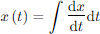
The generic algorithm for each integrator is:
Given

and values at the previous time step

Discretize and integrate with trapezoidal rule formula:

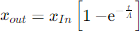
Handling the Exponential (1/(As+1)) Time Delay Block
This is a simple exponential time delay block that shows up in many control block in dynamics analysis and results in a time domain equation of the form:
The generic algorithm for this block is derived as follows:
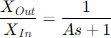
Rearranging:

In the time domain, and discretizing at the nth time step, the derivative of x(t) is computed by:
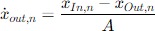
That is, the derivative of the variable of interest – the output variable – is proportional to the difference between the present value of the input and output. Once the derivative is computed, it is integrated in thesame manner as the derivatives for the simple integrator blocks. Here is an example of coding such a time delay block:
procedure Texample.DoActivePController;
begin
Psc_Reg0 := Kcp*(int_P - Pr);
Psc_reg := Limiter(Psc_Reg0, abs(Smax));
Isc_reg := Psc_reg/Vsc;
{Derivatives}
dint_P := ((Pref - Pr) - AWUPp*(Psc_reg0 - Psc_reg))/Tcp;
end;
More complicated s-blocks represented by rational functions can be represented in a similar fashion. Most of the control blocks used in power system simulation are of the two types described here or can be put into those forms.