Example 1
Assume that the Vsource element presents the following parameters:
- Name: TheveninEquivalent
- Nominal Voltage: |E˙AB | = 13.8 kV
- Operating Voltage: |e˙A| = 1.1 pu
- Connection Bus: A
- Connection Configuration: Y g
- Zero Sequence Impedance: Z¯0 = 0.025862916 + j × 0.077588748 Ω
- Positive Sequence Impedance: Z¯1 = 0.023094242 + j × 0.092376969 Ω
The code snippet below presents the circuit element definition with such parameters:
New Circuit.TheveninEquivalent bus1=A pu=1.1 basekv=13.8
~ Z0=[0.025862916,0.077588748] Z1=[0.023094242,0.092376969]
Set voltagebases=[13.8]
Calcvoltagebases
Solve
It is assumed that only the short-circuit powers are known. To assume the same voltage source as above, the short-circuit powers are first calculated from equations (17), (24) and (26) considering the same source characteristics as in the previous example.
It is important to note that OpenDSS only takes the magnitude of the short-circuit powers as input parameters. The angles must be entered indirectly through the x1r1 parameter, which represents the X1/R1 ratio, where R1 and X1 are the positive sequence resistance and reactance, respectively.
With that, the positive sequence impedance and the three-phase short-circuit power can be written as follows.
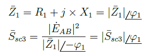
Thus, the three-phase short-circuit power angle can be specified through x1r1 following Equation 29.

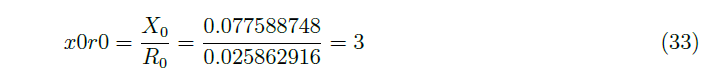
To enter the single-phase short-circuit power angle, x0r0 property is utilized, which represents X0/R0ratio, where R0 and X0 are the zero sequence resistance and reactance, respectively.
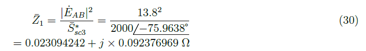
Z¯0 can be calculated from the short-circuit powers. First, Z¯1 is calculated through Equation 30.
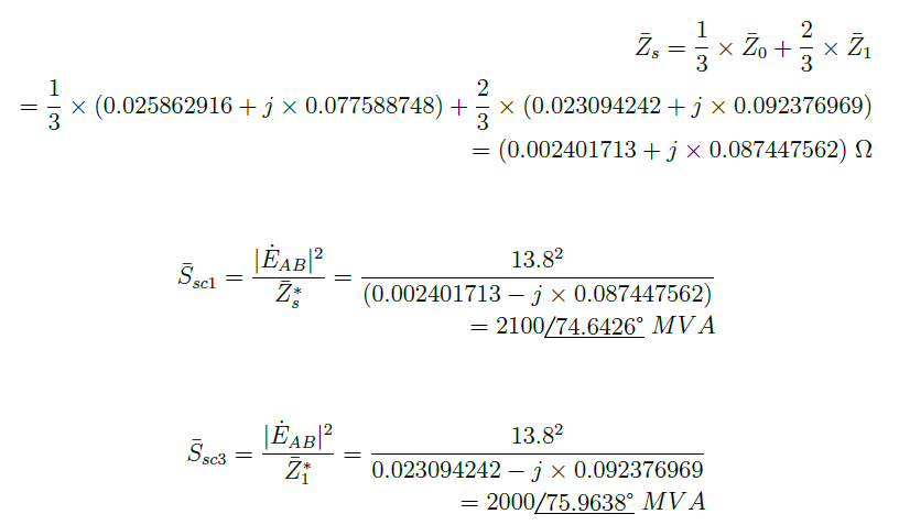
Second, Z¯s is calculated with Equation 31.

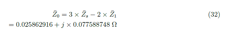
With Z¯1 and Z¯s, Z¯0 can be calculate through Equation 32, which is the result of the manipulation of Equation 26.
Finally, the relation X0/R0 is calculated following Equation 33.
The magnitude of the short-circuit powers and the ratios X0/R0 and X1/R1 are utilized to define the circuit element as follows:
New Circuit.TheveninEquivalent bus1=A pu=1.1 basekv=13.8
~ MVAsc3=2000 x1r1=4 MVAsc1=2100 x0r0=3
Set voltagebases=[13.8]
Calcvoltagebases
Solve
To define the same element but the short-circuit current parameters, those can be obtained from (27) and (28).

As in the short-circuit powers case, the short-circuit currents magnitude and X0/R0 and X1/R1 ratios are used. With the short-circuit currents data I˙sc1 and I˙sc1, the short-circuit powers are calculated with (27) and (28) and, therefore, the method for obtaining X0/R0 and X1/R1 presented above can be used.
The source definition with the short-circuit currents data is presented below:
New Circuit.TheveninEquivalent bus1=A pu=1.1 basekv=13.8
~ Isc3=83674 x1r1=4 Isc1=87858 x0r0=3
Set voltagebases=[13.8]
Calcvoltagebases
Solve