GICLineObject
The GICLine model is used in the calculation of geomagnetically induced current (GIC). Normally, one would think of a Line element as a power delivery device, but in GIC analysis a Line is actually a source. Each phase of the transmission line is represented by a quasi-dc induced voltage (0.1 Hz) in series with the dc resistance of the line. The resulting model is depicted in Figure 1.
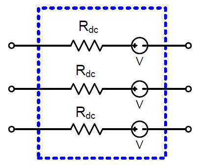
Figure 1. GICLine Model
The induced voltage shown in Figure 49 can be computed internally by the program or supplied via the Volts property of the GICLine model. The following describes the procedure utilized by OpenDSS to compute the induced voltage.
The induced voltage shown in Figure 1 is determined by an application of Faraday’s Law:

where  is the electric field vector at the location of the transmission line, and
  is the incremental line segment length including direction. Because the distance between the source of the induced geoelectric field (electrojet) and the earth’s surface is generally on the order of 100- 200 km, the electric field at the height of the transmission line can assumed to be the same as that of the earth’s surface. If the geoelectric field is assumed constant in the geographical area of a transmission line, then only the coordinates of the end point of the line are important, regardless of routing twists and turns. The resulting incremental length vector , becomes
  .
.
The induced voltage can therefore be computed as follows:

The vector , representing the length and direction of the line between end points can be constructed using an arbitrary reference; however, such methods can introduce error. An improved method is to construct the vector , by computing the distance in the Northward and Eastward directions independently as depicted in Figure 2.
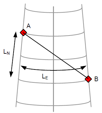
Figure 2. Substation Location Coordinates
Recall that the dot product of two vectors A and B can be computed using:

Thus, the dot product of the induced electric field and the length vector can be approximated by:

where EN is the northward electric field (V/km), EE is the eastward electric field (V/km), LN is the northward distance (km), and LE is the eastward distance (km). The following procedure can be used to compute northward and eastward distances. Consider a transmission line between substations A and B as shown in Figure 50. The northward distance can be computed using:

where Δlat is the difference in latitude (degrees) between the two substations A and B. The eastward distance can be computed using:

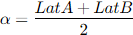
where Δlong is the difference in longitude (degrees) between the two substations A and B, and α is defined as the average of the two latitudes:
The properties of the GICLine model, in order, are:
|
Angle |
Phase angle in degrees of first phase. Default=0.0. See Voltage property |
|
bus1 |
Name of bus for terminal 1. Node order definitions optional. |
|
bus2 |
Name of bus for terminal 2. |
|
C |
Value of line blocking capacitance in microfarads. Default = 0.0, implying that there is no line blocking capacitor. |
|
EE |
Eastward Electric field. If specified, Voltage and Angle are computed from EN, EE, lat and lon values. |
|
EN |
Northward Electric field. If specified, Voltage and Angle are computed from EN, EE, lat and lon values. |
|
frequency |
Source frequency. Defaults to 0.1 Hz. |
|
Lat1 |
Latitude of Bus 1 (degrees) |
|
Lat2 |
Latitude of Bus 2 (degrees) |
|
Lon1 |
Longitude of Bus 1 (degrees) |
|
Lon2 |
Longitude of Bus 2 (degrees) |
|
Phases |
No. of phases. Default = 3. A line has the same number of conductors per terminal as it has phases. Neutrals are not explicitly modeled unless declared as a “phase”, and the impedance matrices must be augmented accordingly. For example, a three-phase line has a 3x3 Z matrix with the neutral reduced, or a 4x4 Z matrix with the neutral retained. |
|
R |
Resistance of line, ohms of impedance in series with GIC voltage source. |
|
Volts |
Voltage magnitude, in volts, of the GIC voltage induced across this line. When spedified, voltage source is assumed defined by Voltage and Angle properties. Specify this value OR EN, EE, lat1, lon1, lat2, lon2. Not both!! Last one entered will take precedence. Assumed identical in each phase of the Line object. |
|
X |
Reactance at base frequency, ohms. Default = 0.0. This value is generally not important for GIC studies but may be used if desired. |
The following properties are common to all Power Conversion elements and inherited by GICLine.
|
like |
Make like another GICLine object |
|
Basefreq |
Inherited Property for all PCElements. Base frequency for specification of the reactance value, X, if defined. |
|
enabled |
{Yes|No or True|False} Indicates whether this element is enabled. Inherited Property for all PCElements. |
|
Spectrum |
Inherited Property for all PCElements. Name of harmonic spectrum for this source. Default is "defaultvsource", which is defined when the DSS starts. Not used for GIC analysis. |