InvControl
OpenDSS inverter modeling has passed through an update, released at the end of 2019. These are mainly related to the new minimum reactive power capability requirements for Distributed Energy Resources (DER) specified in IEEE 1547-2018 [1]. This technical note has been elaborated not only to explain the new features, but also to document how the inverter is modeled in OpenDSS, including all functions available up to date and how the simultaneous operation of several functions is handled. The new features/modifications are:
- Addition of properties %PminNoV ars and %PminkvarMax to provide a region with active power generation/absorption only and a region with ascending linear limit of reactive power, respectively;
- Addition of property %kvarMaxAbs to provide the possibility of having different limits for maximum absorption and maximum generation of reactive power;
- Addition of property PFpriority to enable power factor priority for when the requested operation point is outside the inverter capability curve and for operation under either constant power factor or constant reactive power functions;
- Renaming of some properties names to more suitable ones, in accordance with IEEE 1547-2018 [1];
Up to this date, there is no standalone element for an inverter in OpenDSS. All inverter-related set- tings/functions span over PVSystem and Storage Power Conversion Element (PCE) and InvControl Control Element (CE) models. Even though IEEE 1547-2018 is applicable to DER with different power conversion device technologies such as synchronous machines, induction machines and static power inverters/converters, the features described in this document apply only to the aforementioned OpenDSS PCE. Figure 1 shows the relation between these elements and references [2] and [3] provide a detailed explanation about them.
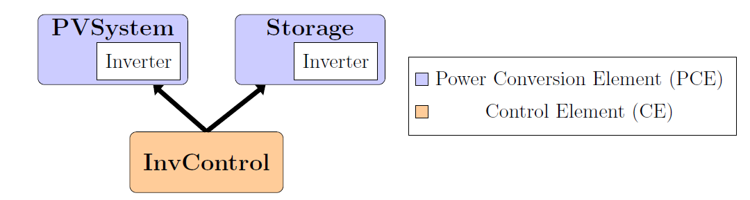
Figure 1: Relation between PVSystem, Storage and InvControl elements
Settings and limits such as apparent power, cut-in/cut-out power and maximum reactive power are modeled within PVSystem and Storage models. These PCEs are also responsible for carrying the definition of other inverter-related parameters, for instance, losses and a few autonomous functions, named as “direct functions” throughout this document. “Direct functions” include constant power factor, constant reactive power (constant kvar) and limit DER power output (commonly used for generation curtailment when power is being generated) functions.
Other functions currently implemented in OpenDSS such as Volt-Var (VV), Volt-Watt (VW) and Dynamic Reactive Current (DRC), referred to in this document as “voltage-dependent functions” are modeled in a separate element, the InvControl CE. The motivation for this approach is that the operation of any PCE at the interface with the grid depends primarily on a nominal power to be injected or absorbed. Because of that, and due to the nature of the constant power factor, constant kvar and limit DER power output functions, they are implemented within the PCE itself. In other words, these functions have all the information they need to set the nominal power at grid the interface before solving a power flow. On the other hand, “voltage-dependent” functions rely on a reference voltage, which means that “voltage-dependent” functions first need a successful power flow solution before assigning new nominal power values to the PCE. Thus, the “voltage-dependent” functions are modeled in InvControl CE. Refer to [4] and [5] for more information about how OpenDSS models control elements and manages the operation of multiple control elements during the simulation.
This document first describes the modeling of the inverter capability curve and its associated parameters by showing the most general shape of the curve, including possible modifications to its shape and how OpenDSS handles cases in which the requested complex power violates it. A quick explanation of how the inverter efficiency curve is modeled is also given. Then, all inverter-related functions currently modeled are briefly presented and segmented by the specific elements in which each of them can be defined in OpenDSS scripting language. Next, the precedence rules of settings and functions are presented along with an explanation about which functions are mutually exclusive and which can operate simultaneously. Finally, a few commented examples are provided.