Inverter Capability Curve
The most flexible inverter capability curve is presented in Figure 2. All measures are on the AC side of the inverter. Note that %CutIn and %CutOut have been assumed equal. If that’s not the case, once the inverter is on, only %CutOut is considered.
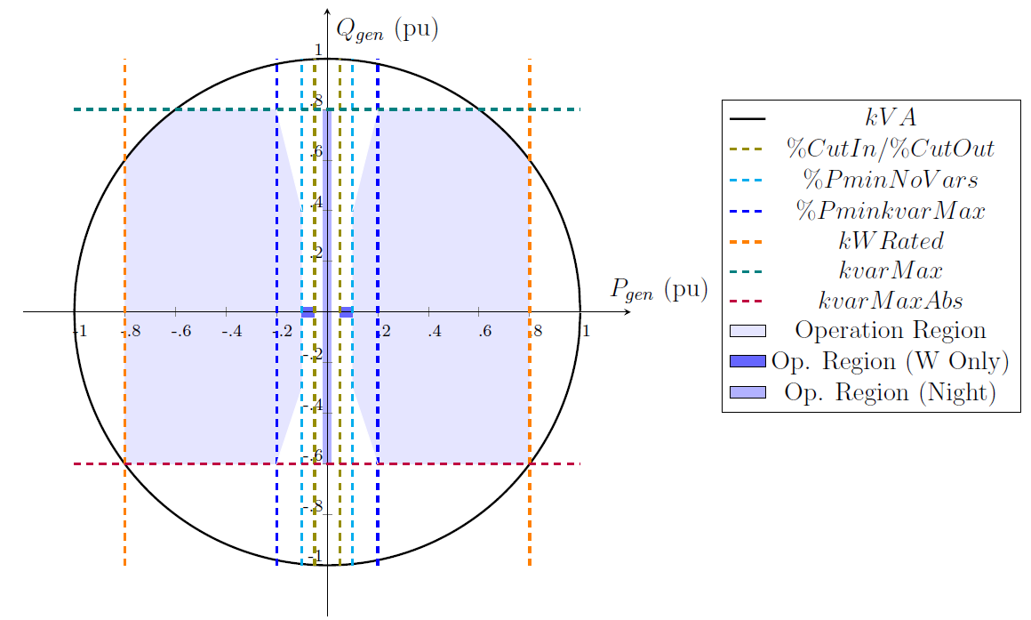
Figure 2: General Inverter Capability Curve
The following properties are utilized to define the inverter capability curve:
- kV A [kVA]: indicates the inverter nameplate capability. For PVSystem, it serves as the default value for kvarMax and kvarMaxAbs properties in case they are not specified. For Storage, this property is automatically set to kWRated whenever kV A has not been specified yet. Defaults to 500 for PVSystem and to kWRated for Storage.
- kWRated [kW]: indicates the maximum active power that the DER can deliver to the grid. It is currently available only for Storage element. Defaults to 25. Meanwhile for PVSystem, the same effect (limit on active power delivered) can be obtained through property %Pmpp (see subsection 8.1).
- kvarMax [kvar]: Indicates the maximum reactive power generation (unsigned numerical variable in kvar) for the inverter. Defaults to kV A rating of the inverter.
- kvarMaxAbs [kvar]: Indicates the maximum reactive power absorption (unsigned numerical variable in kvar) for the inverter. Defaults to kvarMax.
- %CutIn [unit-less]: cut-in power as a percentage of inverter kVA rating. It is the minimum DC power necessary to turn the inverter ON when it is OFF. Must be greater than or equal to %CutOut. Defaults to 2 for PVSystems and 0 for Storage elements which means that the inverter state will be always ON for this element. %CutIn in Figure 2 represents the specified %CutIn adjusted by inverter losses, i.e., the equivalent %CutIn at the AC side of the inverter.
- %CutOut [unit-less]: cut-out power as a percentage of inverter kVA rating. It is the minimum DC power necessary to keep the inverter ON. Must be less than or equal to %CutIn. Defaults to 2 for PVSystems and 0 for Storage elements which means that, once ON, the inverter state will be always ON for this element. %CutOut in Figure 2 represents the specified %CutOut adjusted by inverter losses, i.e., the equivalent %CutOut at the AC side of the inverter.
- %PminNoVars [unit-less]: minimum active power as percentage of kWrated for Storage and as percentage of Pmpp for PVSystem under which there is no reactive power production/absorption. Defaults to 0 (disabled).
- %PminkvarMax [unit-less]: minimum active power as percentage of kWrated for Storage and as percentage of Pmpp for PVSystem that allows the inverter to produce/absorb reactive power up to its maximum reactive power, which can be either kvarMax or kvarMaxAbs, depending on the current operation quadrant. Defaults to 0 (disabled).
- varFollowInverter [True/False]: Defaults to False, which indicates that the reactive power generation/absorption does not respect the inverter status. When set to True, the reactive power generation/absorption will cease when the inverter status is off, due to DC kW dropping below %Cutout. The reactive power generation/absorption will begin again when the DC kW is above %Cutin. When set to False, the storage will generate/absorb reactive power regardless of the status of the inverter.