Operation in Power-Flow Driven Modes
The controller operation is essentially the same in all the different power flow-driven modes. The operation is illustrated in Figure 7, where the blocks in green work differently for charging and dis- charging modes. This algorithm is executed every control iteration (see [3], [4] and [5] for an overview of how OpenDSS handles control elements). It is important to note that there is no time delay involved in the operation of this control element, which could represent for instance, communication delays 1. This means that the actions pushed to the control queue are executed at the same simulation time in all control modes (static, time, etc), see the OpenDSS manual [4] for more information on different control modes. Its convergence criteria is satisfied when no other action is pushed to the control queue, which is determined by not setting either power or state changes to any storage element of the fleet.
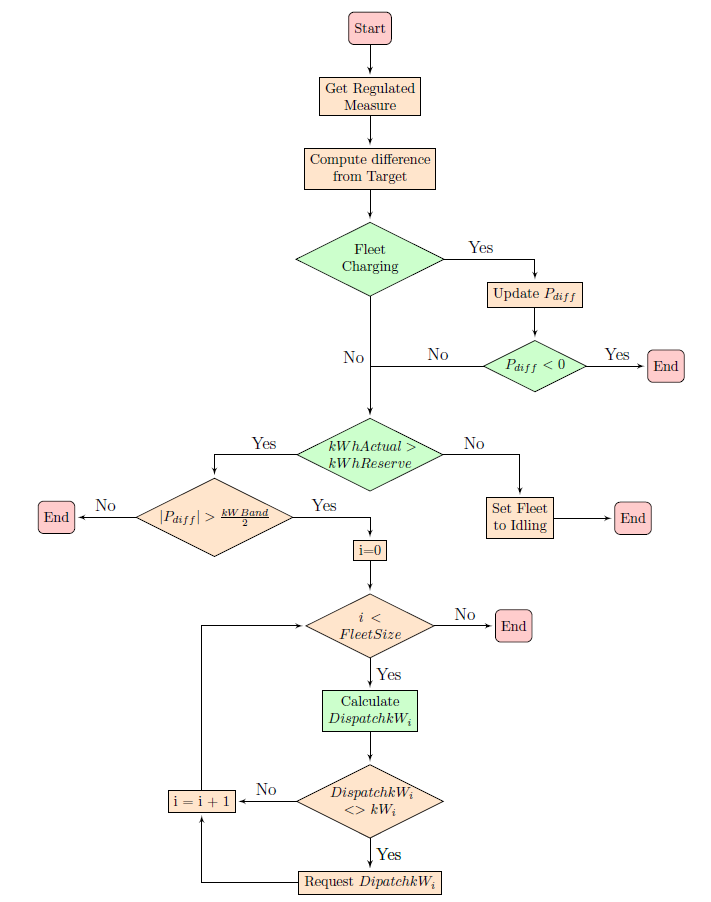
Figure 7: Algorithm for “power flow-driven” dispatch modes run at every control iteration and assuming discharging modes (in charging modes, the implementation differs for the green blocks).
Each block is detailed below:
- Get Regulated Measure: The regulated measure, Preg, for power, or Ireg, for current, is calculated based on the power/current flowing into the terminal Terminal of the monitored element Element and the monitored phase or combination of phases specified in MonPhase from the most recent successful power flow solution;
- Compute difference from Target: The power/current difference between the regulated measure and the target is the error that the controller tries to reduce to a value within kWBand. Its calculation depends on the selected dispatch mode and it is direction dependent2 as explained below.
(a) PeakShave (PeakShaveLow) and Follow: Pdiff = Preg − kWTarget(kWTargetLow) Note that the regulated power is assumed to be normally positive, i.e, a Pdiff greater than kWBand/2 leads the controller to request the fleet to discharge an amount of Pdiff in order to limit Preg to kWTarget, for discharging modes. For charging modes, a negative Pdiff leads the controller to request the fleet to charge the same amount.
(b) I-PeakShave (I-PeakShaveLow): Pdiff = Ireg − kWTarget(kWTargetLow)
Same idea as for PeakShave and Follow modes, except that all variables represent current magnitude rather than active power.
(c) Support: Pdiff = Preg + kWTarget
In support mode, as commented in 5.1.4, the regulated power is assumed to be normally negative. Thus, Pdiff is calculated based on the sum of Preg and the target, such that a regulated power less than kWTarget leads to a positive Pdiff , which leads the controller to discharge the fleet.
After calculating Pdiff , its value is stored in StorageController’s kWneed read-only property, which is accessible to the user. See Table 3 for a list of all properties available.
- Fleet Charging (for Discharging Modes): This block is necessary to make sure that the con- troller will not inadvertently try to dispatch the fleet because of the increase in Preg/Ireg due to the power it consumes while in charging state. Thus, the power being consumed by the fleet is discounted from Pdiff and it is updated as shown below:
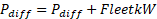
where FleetkW is the total power currently being charged/discharged by the fleet, following the generator convention. If the updated Pdiff is negative, the controller does not send any dispatch request to the fleet. In other words, any overloading due to charging is ignored by the controller, which may lead to a situation in which Preg is greater than kWTarget by a value greater than kWBand and the controller will still not try to dispatch the fleet. The purpose of this mechanism is to make sure the controller will not affect the charging of the fleet, otherwise there might not be enough energy stored to discharge the fleet when needed. Nonetheless, the total power consumed by the fleet during charging can be controlled by the available charging dispatch modes and configured such that kWtarget is not surpassed during charging instants.
For charging modes, the condition is changed to check whether the fleet state is Discharging. The basic idea is the same. In this case, to avoid Pdiff to be negative due to the decrease in Preg while discharging, because if the fleet discharges (FleetkW > 0), Preg tends to decrease and may inadvertently trigger the controller to charge the fleet. Thus, for charging modes, if the updated Pdiff is positive, the controller does not send any dispatch request to the fleet.
- kWhActual > kWhReserve (for Discharging Modes): For discharging modes, if the fleet is already in discharging state or in case it is not but Pdiff is positive, the controller might send new dispatch values to each element of the fleet if some conditions are met. First, the total energy stored by the fleet, kWhActual must be greater than the total reserve energy, kWhReserve, otherwise the fleet is just set to idling state. In case the current fleet state is not idling and this condition is not satisfied, an action is pushed to the control queue, forcing a new iteration of the controller.
For charging modes, if the fleet is already in charging state or in case it is not but Pdiff is negative, the first condition modifies to check whether there is enough capacity left to charge the fleet, i.e., kWhActual must be less than the total energy capacity, kWhTotal, otherwise the fleet is just set to idling state.
- |Pdiff | > kWBand / 2: The second condition verifies if the absolute value of Pdiff is out of the deadband or not. This is where the controller algorithm usually ends in its last control iteration if the available power and energy of the fleet are enough to perform the requested action (fully shave the peak, fully fill the valley, fully support a generator, etc).
- Calculate DispatchkWi: If Pdiff is not within the band, the controller iterates over all storage elements of the fleet and calculates an incremental power, ∆Pi to be requested to each element of the fleet, i, according to
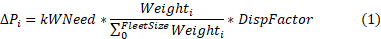
where FleetSize corresponds to the total number of storage under control of this control element, Weighti corresponds to the weight given to a particular storage through Weights property and DispFactor is a property added to aid in eventual convergence issues that might happen to the controller. It reduces the incremental power requested to each storage element of the fleet in order to slowly move Preg/Ireg towards kWTarget. It is suggested to not play with this property unless control loop convergence issues have been identified as being caused by the StorageController element.
For I-PeakShave and I-PeakShaveLow modes, kWNeed is converted from current to power based on the number of phases and the rated voltage of each element, i, of the fleet.
Then, the incremental power is added to the nominal power currently being dispatched by the storage element i, PresentkWi, which already satisfies any constraints in the nominal active output power due to the inverter capability curve. See [6]. However, the final requested dispatch is limited to the rated active power of the inverter, kWRating, which can be written as

for discharging modes, and

for charging modes, if PresentkWi + ∆Pi is negative. Note that it assumes that the inverter active power rating is the same for charging and discharging.If in equations (2) and (3) the resulting power is negative and positive, respectively, the storage element i is just set to idling state instead.
- DispatchkWi <> kWi: The request of the recently calculated DispatchkWi is only sent to the storage element i if it is actually different from the previous request sent, kWi. This condition is necessary so that the controller will not end up in an infinite loop when there is no power enough in the fleet to regulate the power or current to the desired target. If that is the case, the algorithm does not request any change to the element i.
- Send DispatchkWi: Finally, if there has been a change, the controller requests a new power to be dispatched by the storage element. In this case it also pushes a new action to OpenDSS control queue (see [5]) to force a new control iteration.
Note that the requested power may not be the actual power delivered in the next power flow solution, since the final P and Q combination must satisfy the constraints imposed by the inverter capability curve (note that the element might also be operating with a reactive power dispatch mode that also requests some vars). The requested kW and the actual delivered kW in each control iteration can be checked in the event log report, as shown in example 7.1.
1In particular, StorageController is assumed to operate as fast as InvControl element, i.e., when operating together, their control actions are executed simultaneously.
2The appropriate terminal, terminal, of the monitored element, element, must be selected according to the dispatch mode and based on the expected power flow direction for the monitored element. Power flowing into the monitored terminal defines the sign of Preg.