Relay Directional Overcurrent Element
1. Purpose
This technical note describes the modeling of a Directional Overcurrent (DOC) relay function as part of the Relay Model of OpenDSS. It also describes how the model can be parameterized to represent standard and non-standard trip functions. Some examples are also provided.
2. Why?
This relay element was initially implemented to expand on the existing reversepower mode of operation of the relay model in OpenDSS. It is mainly intended to model multiple Network Protector (NWP) reverse flow operation options but it is not restricted to that application.
3. Brief Introduction
This relay mode of operation is intended for applications where not only current magnitudes determine operation and trip times but also the angle determines the region of operation or whether the relay operates at all.
It has been originally implemented to mimic features of microprocessor network protector relays for reverse power flow. It includes network protector functionalities as described in the IEEE standard C57.12.44-2014 [1]. These applications should allow for reverse power flow under certain operating scenarios and trip for reverse fault conditions while forward current flow operation is restrained. Nevertheless, this relay mode can also be used to model DOC protection applications where, for instance, the backward current flow direction is restrained and the relay is supposed to trip and protect a faulted line only in the forward direction.
The modes of operation include a sensitive reverse flow mode intended to trip for any reverse flow condition where reverse resistive currents exceed a given pickup threshold, regardless of reactive current components. The sensitive region of operation can also be defined by a threshold line tilted around user-defined resistive current values by user-defined angles. The relay model also includes regions of operation defined by current magnitudes. The combination of regions of operation can be used to allow reverse flow for defined time intervals or indefinitely as long as the current stays in defined regions. Trip times can also be defined by inverse Time-Current Curve (TCC) curves.
Operation region options can be combined depending on the application. The details on each mode of operation and the associated parameters are provided in this tech note.
4. Modeling
The different operation regions are defined over a polar diagram of phase current having the corresponding phase voltage angle as reference. The reference voltage is determined by the monitored terminal of the monitored element of the relay instance. Similarly, the monitored currents are those
flowing into the monitored terminal of the monitored element, i.e., the typical convention adopted in OpenDSS for monitoring devices and reported quantities.
Various parameters allow for a flexible customization of the operation region or regions. Figure 1 presents the most generic relay characteristics that can be achieved. As previously mentioned, the angles in the relay characteristic are referenced with respect to the voltage angle, for each monitored phase.
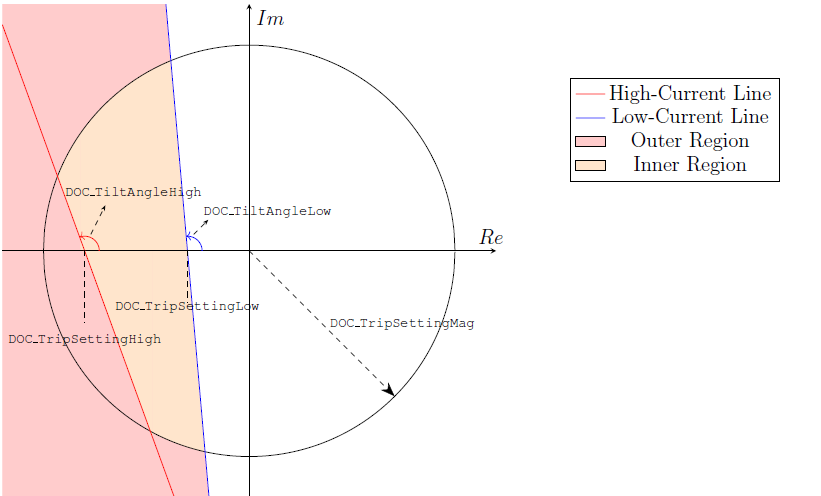
Figure 1: Generic Directional Overcurrent (DOC) Relay Characteristic
The following parameters are utilized to define the relay characteristic:
• DOC_TripSettingLow: trip setting for a resistive low current. Defines the low-current line in conjunction with DOC_TiltAngleLow. Its default value is 0.
• DOC_TiltAngleLow: angle of low-current line with respect to resistive current axis. Defines the low-current line in conjunction with DOC_TripSettingLow. Its default value is 90 degrees.
• DOC_TripSettingHigh: trip setting for a resistive high current. Defines the high-current line in conjunction with DOC_TiltAngleHigh. Utilized when the relay characteristic to be modeled requires the use of two lines. Defaults to -1, meaning that the line is deactivated. Must be set to a positive value to be activated.
• DOC_TiltAngleHigh: angle of high-current line with respect to resistive current axis. Defines the high-current line in conjunction with DOC_TripSettingHigh. Its default value is 90 degrees. This property has no effect if DOC_TripSettingHigh is deactivated.
• DOC_TripSettingMag: trip setting for current magnitude. It can be used to define an inner region for the relay characteristics. Deactivated by default (-1 value). Must be set to a positive value to be activated.
In DOC mode, an extra property, DOC_P1Blocking, must be utilized in order to block the element trip when the total net balanced (positive sequence) active power flows in the forward direction. By default, this property is set to True, conforming to IEEE standard C57.12.44-2014 [1].
In addition to these properties, there are two sets of properties that determine the trip time for each region. The first set leverages existing properties (also utilized in other modes of operation such as current and voltage) of the OpenDSS relay element and are utilized in two cases: 1) when a low current line is utilized only (i.e., there is a unique region described by the relay characteristics), or 2) when two regions are defined, which happens when the current magnitude trip setting or the high-current line are specified. These properties are described below:
• Delay: trip time delay when low current lines is utilized only or for outer region when both high-current and low-current lines are specified. Defaults to 0, meaning a instantaneous trip. If PhaseCurve is specified, this property is ignored.
• PhaseCurve: TCC determining the element trip time when low-current line is utilized only or for outer region when both high and low current lines are specified. There is no default.
• PhaseTrip: multiplier for the PhaseCurve TCC curve. Defaults to 1.0.
• TDPhase: time dial for PhaseCurve TCC curve, a multiplier on the time axis of the specified curve. Defaults to 1.0
The second set of properties are utilized when the element operates specifically in the DOC mode. For this reason, their names are prefixed with “DOC”. These properties determine the trip setting in the inner region only, i.e., they are applied when DOC_TripSettingMag or DOC_TripSettingHigh are activated. These properties are described below:
• DOC_DelayInner: trip time delay for operation in inner zone. When set to 0, it specifies an instantaneous trip. When set to a negative number, it specifies an insensitive (i.e., no trip) element. A positive numbers specified a definite time delay in the inner region. If DOC_PhaseCurveInner is specified, this property is ignored.
• DOC_PhaseCurveInner: TCC determining the element trip time in the inner region. There is no default.
• DOC_PhaseTripInner: multiplier for the DOC_PhaseCurveInner TCC curve. Defaults to 1.0.
• DOC_TDPhaseInner: time dial for DOC_PhaseTripInner TCC curve, a multiplier on the time axis of the specified curve. Defaults to 1.0
5. Standard and Non-Standard Functions
This section describes how the relay element can be utilized to model standard [1] and non-standard functions.
5.1 Standard - Sensitive Trip
The standard sensitive trip function is described by a resistive current trip setting with an adjustable tilt angle, as shown in Figure 2. This is the typical network protector operating mode where power flow is expected to be from source end to load end towards the low voltage meshed network. Minimum trip settings are typically 0.05% to 0.1% of the network protector rating, depending on the relay type (electromechanical or microprocessor). 0.15%-0.2% are more common values. The reverse trip setting should be only as low as required to assure automatic opening when the primary feeder breaker is opened. Very low values can cause unnecessary operations due to transient reverse power flows — the relay would be too sensitive.
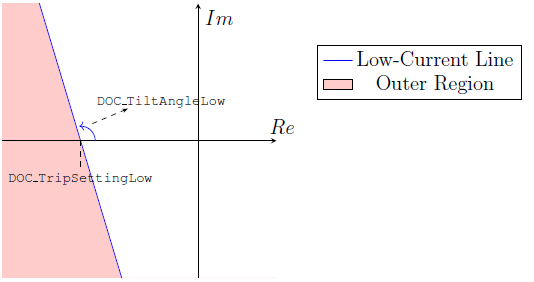
Figure 2: Sensitive Trip Characteristic
The Delay property must be utilized to specify a definite time delay trip. An instantaneous trip can be specified by setting this property to 0. A TCC-based delay can be specified through the properties PhaseCurve, PhaseTrip and TDPhase.
The script below indicates how OpenDSS must be parameterized to model this standard function for a trip setting of 5A and a tilt angle of 90◦.
DOC Relay with Standard Sensitive Trip Function
New Relay.MyDOCRelay monitoredobj=Line.MyMonitoredLine type=DOC
˜ DOC_TiltAngleLow=90 DOC_TripSettingLow=5 delay=0
5.2 Standard - Time Delay Trip
The standard time delay trip allows for low-current reverse power flow conditions for a determined time range, and an instantaneous trip for high-current reverse power flow conditions, as shown in Figure 3.

Figure 3: Time Delay Trip Characteristic
According to [1], for this mode of operation, the instantaneous trip region should be adjustable for currents from 50% to 200% of the network protector current transformer rating. In OpenDSS, the instantaneous trip setting is specified through the DOC_TripSettingMag property.
This function can be modeled in OpenDSS according to the following script, for a low-current trip setting of 5A and tilt angle of 90◦ and an instantaneous trip setting of 40A. In this sample snippet, the delayed trip setting has been set to 2.5 minutes.
! DOC Relay with Standard Time Delay Trip Function
New Relay.MyDOCRelay monitoredobj=Line.MyMonitoredLine type=DOC
˜ DOC_TiltAngleLow=90 DOC_TripSettingLow=5 DOC_TripSettingMag=40 ! Trip Settings
˜ delay=0 DOC_DelayInner=150 ! Delay Settings
5.3 Standard - Insensitive Trip
This function is similar to the delayed trip function, except that the element allows for continuous operation in the inner region without delayed trip, i.e., it only trips for instantaneous OC, as shown in Figure 4.
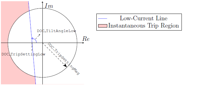
Figure 4: Insensitive Trip Characteristic
To accomplish this behavior, the inner region delay must be set to a negative number, as shown below.
! DOC Relay with Standard Insensitive Trip Function
New Relay.MyDOCRelay monitoredobj=Line.MyMonitoredLine type=DOC
˜ DOC_TiltAngleLow=90 DOC_TripSettingLow=5 DOC_TripSettingMag=40 ! Trip Settings
˜ delay=0 DOC_DelayInner=-1 ! Delay Settings. Trip in inner region is off
5.4 Non-Standard - Modified Insensitive Trip
The settings in this mode of operation are included to support future developments. They are intended to provide an extra degree of freedom for defining the instantaneous and time delayed trip regions.
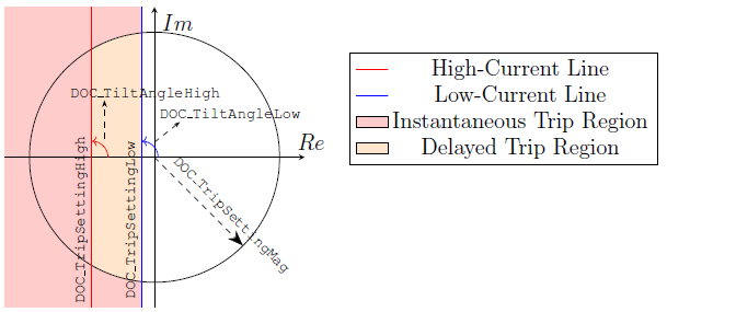
Figure 5: Modified Insensitive Trip Characteristic
6. Examples
In this section, several examples are presented to show the operation of the DOC element. To facilitate this, the IEEE 342-Node (Low voltage Network Test System) is utilized [2]. A version of this test model is included within the IEEETestCases folder in OpenDSS.
The topology of this test is shown in Figure 6. This test case can be described as follows:
• 1 Low Voltage (LV) grid operated at 216 V , fed by 48 network transformers. In Figure 6, this LV grid network is highlighted with gray background and with conductors in black.
• 8 LV spot networks operated at 480 V , fed by 20 network transformers. Four of these spot networks are supplied through network transformers while the other four are supplied through 2 network transformers. In Figure 6, these spot networks are highlighted with a green background and are enumerated to facilitate navigation – SN# indicates spot network and its number.
• All 68 network transformers are fed by 8 Medium Voltage (MV) feeders operated at 13.8 kV . These feeders are enumerated and displayed with different colors in Figure 6.
• The 8 MV feeders are fed by 2 substation transformers with Delta connections on both primary and secondary windings. These are fed by a source operated at 230 kV .
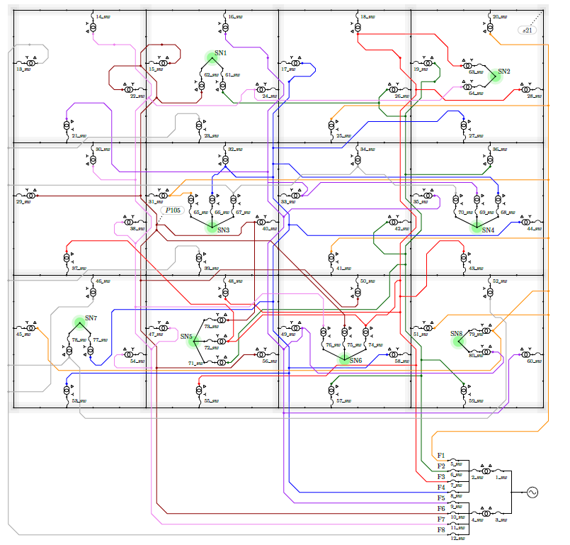
Figure 6: Single-Line Diagram of the IEEE 342-Node Test Case
• All network transformers have Wye-Delta winding connections with Delta on the primary side.
• A total of 624 single-phase Loads are connected to the LV networks.
For the purposes of this technical note, the network protectors have been modeled using the following
assumptions to define their settings.
• Network protectors associated with network transformers serving spot networks (480 V ) are assigned with CT primary ratings of 3500 A if the transformers are of the following ratings: 2000 kV A and 2500 kV A. This corresponds to a total of 18 network protectors. The remaining 2 network transformers are rated at 1000 kV A and their associated network protectors are assigned with CT primary ratings of 1600 A.
• All other network protectors are associated to network transformers serving the Low Voltage (LV) grid (216 V ). These are all rated at 1000 kV A and their network protectors are assigned CT primary ratings of 3500 A.
• All network protectors are by default set to sensitive trip mode with instantaneous trip setting set to 0.15% of their primary CT rating, i.e., DOC_tripsettinglow=(3500 @nwp_inst_ct_pu *) where @nwp_inst_ct_pu is a global DSS variable set to 0.0015, for a CT rating of 3500 A.
• A typical tilt angle of 95 degrees is used for doc_tiltanglelow.
The DSS scripts for all examples below are available in your local OpenDSS installation examples folder “DOCTechNote” subfolder. All example scripts first redirect to another dss file “DOCTech- Note/ExamplesMaster.dss”, shown below.
! Load Master Model from Local OpenDSS
Redirect "C:\Program Files\OpenDSS\IEEETestCases\LVTestCaseNorthAmerican\Master.dss"
! Load Network Protectors
Redirect "C:\Program Files\OpenDSS\IEEETestCases\LVTestCaseNorthAmerican\network_protectors.dss"
! Load Energy Meters
Redirect "C:\Program Files\OpenDSS\IEEETestCases\LVTestCaseNorthAmerican\energy_meters.dss"
BatchEdit Relay..* debugtrace=yes
As one can see below, this script essentially loads the original IEEE 390 node model provided in OpenDSS “IEEETestCases/LVTestCaseNorthAmerican” folder, plus the DSS files containing the definition of the network protectors, the energy meters — for a better visualization of the different networks in the model. Finally it also includes a batch edit command for enabling the debug trace property of all network protectors to generate a detailed report in the event log.
6.1 Events on the Low-Voltage Level
In the following examples, fault events are applied in different LV buses. Since the faults are downstream all network protectors, none of them are expected to trip.
6.1.1 SLG Fault on LV Grid Network
In this example, a SLG fault is applied at the top right corner bus at the LV grid network, “S21” as shown in Figure 6.
! Example 1.1 Fault on the 2ndary grid network
Redirect "C:\Program Files\OpenDSS\Examples\DOC_TechNote\ExamplesMaster.dss"
! SLG Fault on Bus S21 - Top Right Corner of LV network
New Fault.fault bus1=S21.1 bus2=S21.0 phases=1 r=0.0001
Solve
Show eventlog
As the event log results files show — the user is encouraged to run the simulations — none of the network protectors trip since there is no positive sequence active power reverse flow in any of the network protectors, as expected.
6.1.2 SLG Fault on LV Spot Network
In this example, a SLG fault is applied at the LV spot network 3, at bus “S203”. The faulted spot network is highlighted in green background with label SN3 in Figure 6.
! Example 1.2 Fault on the 2ndary spot network
Redirect "C:\Program Files\OpenDSS\Examples\DOC_TechNote\ExamplesMaster.dss"
! SLG Fault on Bus S203 (Spot Network 3)
New Fault.fault bus1=S203.1 bus2=S203.0 phases=1 r=0.0001
Solve
Show eventlog
Again, and as expected, none of the network protectors is sensitized since the fault is downstream all of them.
6.2 Events on the Medium-Voltage Level
In the following examples, events are applied in the MV primary feeder 6, displayed in brown color and labeled F6 in Figure 6. Both events lead to reverse power flow in the network protectors at the service transformers connected to this feeder. As it can seen on Figure 6, feeder 6 serves 6 network transformers supplying the LV grid and 3 network transformers serving spot networks SN1, SN5 and SN6.
6.2.1 Out of Service Feeder
In this example, feeder 6 is taken out of service by opening its feeder head breaker. This simulates, for example, the maintenance of such feeder, as well as the response to a fault. The script for this example is shown below.
! Example 2.1 Feeder Out of Service
Redirect "C:\Program Files\OpenDSS\Examples\DOC_TechNote\ExamplesMaster.dss"
! Feeder 6 Out of Service
Open Line.10_sw ! Open feeder breaker
Solve
Show eventlog
A short version of the generated event log report is presented below.
Hour=0, Sec=0, ControlIter=1, Element=Relay.75_sw, Action=OPENED ON DOC & LOCKED OUT
Hour=0, Sec=0, ControlIter=1, Element=Relay.56_sw, Action=OPENED ON DOC & LOCKED OUT
Hour=0, Sec=0, ControlIter=1, Element=Relay.50_sw, Action=OPENED ON DOC & LOCKED OUT
Hour=0, Sec=0, ControlIter=1, Element=Relay.40_sw, Action=OPENED ON DOC & LOCKED OUT
Hour=0, Sec=0, ControlIter=1, Element=Relay.29_sw, Action=OPENED ON DOC & LOCKED OUT
Hour=0, Sec=0, ControlIter=2, Element=Relay.22_sw, Action=OPENED ON DOC & LOCKED OUT
Hour=0, Sec=0, ControlIter=2, Element=Relay.15_sw, Action=OPENED ON DOC & LOCKED OUT
Hour=0, Sec=0, ControlIter=3, Element=Relay.73_sw, Action=OPENED ON DOC & LOCKED OUT
Hour=0, Sec=0, ControlIter=4, Element=Relay.62_sw, Action=OPENED ON DOC & LOCKED OUT
Note that the event log indicates that all 9 the network protectors associated with the service transformers connected to this feeder tripped. This is an expected and adequate behavior. It occurs due to the low reverse power trip setting, which trips the network protectors mainly due to the losses associated with the respective service transformers and cable charging current, and to circulating currents [1].
Furthermore, the event log sequence of events also shows that not all network protectors trip at the same time. Network protectors 75, 56, 50, 40 and 29 are the first ones to trip for reverse powerflow. This is because the reverse power flow in all network protectors is not sufficient to trip all of them simultaneously. However, once the first set of network protectors trip, a cascading effect occurs because the reverse power flow associated with the first set of tripped network protectors continue to be energized through the remaining network protectors. Thus, the total losses in the open feeder are supplied through the protectors that remain closed, pushing them towards the tripping region.
In the above example, network protectors 22 and 15 are the second ones to trip, followed by 73 and 62.
6.2.2 LL Fault on MV Feeder
In this example, a LL fault is applied at the MV bus “P105”. For simplicity, OC relays are added to the feeder head breakers for all feeders with a 20kA trip setting with definite 0.1 seconds delay. The relays were added to make sure that the applied fault will be isolated.
The control mode has been set to event so that the time instant of the executed control actions are recorded in the event log.
! Example 2.2 LL Fault on the MV Primary Network
Redirect "C:\Program Files\OpenDSS\Examples\DOC_TechNote\ExamplesMaster.dss"
! Adding OC relays to feeder breakers
New Relay.F6 monitoredobj=Line.10_sw type=current delay=0.1 PhaseTrip=20000 RecloseIntervals=None
New Relay.F7 monitoredobj=Line.11_sw type=current delay=0.1 PhaseTrip=20000 RecloseIntervals=None
New Relay.F8 monitoredobj=Line.12_sw type=current delay=0.1 PhaseTrip=20000 RecloseIntervals=None
New Relay.F1 monitoredobj=Line.5_sw type=current delay=0.1 PhaseTrip=20000 RecloseIntervals=None
New Relay.F2 monitoredobj=Line.6_sw type=current delay=0.1 PhaseTrip=20000 RecloseIntervals=None
New Relay.F3 monitoredobj=Line.7_sw type=current delay=0.1 PhaseTrip=20000 RecloseIntervals=None
New Relay.F4 monitoredobj=Line.8_sw type=current delay=0.1 PhaseTrip=20000 RecloseIntervals=None
New Relay.F5 monitoredobj=Line.9_sw type=current delay=0.1 PhaseTrip=20000 RecloseIntervals=None
! LL Fault on Bus p105 (Feeder 6)
New Fault.fault bus1=p105.1 bus2=p105.2 phases=1 r=0.0001
Set controlmode=event ! To visualize tripping times in event log
Solve
Show eventlog
A short version of the event log is shown below. Note that a total of 34 network protectors trip. This includes the 9 network protectors directly connected to feeder 6, but also all network protectors associated with the adjacent feeders 5, 7 and 8, which backfeed the fault at feeder 6 through the LV networks all the way to the bus bar at the primary substation.
Hour=0, Sec=0, ControlIter=1, Element=Relay.80_sw, Action=OPENED ON DOC & LOCKED OUT
Hour=0, Sec=0, ControlIter=1, Element=Relay.78_sw, Action=OPENED ON DOC & LOCKED OUT
Hour=0, Sec=0, ControlIter=1, Element=Relay.76_sw, Action=OPENED ON DOC & LOCKED OUT
Hour=0, Sec=0, ControlIter=1, Element=Relay.73_sw, Action=OPENED ON DOC & LOCKED OUT
Hour=0, Sec=0, ControlIter=1, Element=Relay.70_sw, Action=OPENED ON DOC & LOCKED OUT
Hour=0, Sec=0, ControlIter=1, Element=Relay.69_sw, Action=OPENED ON DOC & LOCKED OUT
Hour=0, Sec=0, ControlIter=1, Element=Relay.67_sw, Action=OPENED ON DOC & LOCKED OUT
Hour=0, Sec=0, ControlIter=1, Element=Relay.64_sw, Action=OPENED ON DOC & LOCKED OUT
Hour=0, Sec=0, ControlIter=1, Element=Relay.60_sw, Action=OPENED ON DOC & LOCKED OUT
Hour=0, Sec=0, ControlIter=1, Element=Relay.56_sw, Action=OPENED ON DOC & LOCKED OUT
Hour=0, Sec=0, ControlIter=1, Element=Relay.54_sw, Action=OPENED ON DOC & LOCKED OUT
Hour=0, Sec=0, ControlIter=1, Element=Relay.52_sw, Action=OPENED ON DOC & LOCKED OUT
Hour=0, Sec=0, ControlIter=1, Element=Relay.50_sw, Action=OPENED ON DOC & LOCKED OUT
Hour=0, Sec=0, ControlIter=1, Element=Relay.49_sw, Action=OPENED ON DOC & LOCKED OUT
Hour=0, Sec=0, ControlIter=1, Element=Relay.47_sw, Action=OPENED ON DOC & LOCKED OUT
Hour=0, Sec=0, ControlIter=1, Element=Relay.46_sw, Action=OPENED ON DOC & LOCKED OUT
Hour=0, Sec=0, ControlIter=1, Element=Relay.39_sw, Action=OPENED ON DOC & LOCKED OUT
Hour=0, Sec=0, ControlIter=1, Element=Relay.38_sw, Action=OPENED ON DOC & LOCKED OUT
Hour=0, Sec=0, ControlIter=1, Element=Relay.35_sw, Action=OPENED ON DOC & LOCKED OUT
Hour=0, Sec=0, ControlIter=1, Element=Relay.34_sw, Action=OPENED ON DOC & LOCKED OUT
Hour=0, Sec=0, ControlIter=1, Element=Relay.33_sw, Action=OPENED ON DOC & LOCKED OUT
Hour=0, Sec=0, ControlIter=1, Element=Relay.30_sw, Action=OPENED ON DOC & LOCKED OUT
Hour=0, Sec=0, ControlIter=1, Element=Relay.24_sw, Action=OPENED ON DOC & LOCKED OUT
Hour=0, Sec=0, ControlIter=1, Element=Relay.23_sw, Action=OPENED ON DOC & LOCKED OUT
Hour=0, Sec=0, ControlIter=1, Element=Relay.21_sw, Action=OPENED ON DOC & LOCKED OUT
Hour=0, Sec=0, ControlIter=1, Element=Relay.16_sw, Action=OPENED ON DOC & LOCKED OUT
Hour=0, Sec=0, ControlIter=1, Element=Relay.14_sw, Action=OPENED ON DOC & LOCKED OUT
Hour=0, Sec=0, ControlIter=1, Element=Relay.13_sw, Action=OPENED ON DOC & LOCKED OUT
Hour=0, Sec=0, ControlIter=2, Element=Relay.40_sw, Action=OPENED ON DOC & LOCKED OUT
Hour=0, Sec=0, ControlIter=2, Element=Relay.29_sw, Action=OPENED ON DOC & LOCKED OUT
Hour=0, Sec=0, ControlIter=2, Element=Relay.22_sw, Action=OPENED ON DOC & LOCKED OUT
Hour=0, Sec=0, ControlIter=2, Element=Relay.15_sw, Action=OPENED ON DOC & LOCKED OUT
Hour=0, Sec=0.1, ControlIter=3, Element=Relay.feeder_6, Action=OPENED ON PH & LOCKED OUT
Hour=0, Sec=0.1, ControlIter=3, Element= , Action=PHASE TARGET
Hour=0, Sec=0.1, ControlIter=4, Element=Relay.75_sw, Action=OPENED ON DOC & LOCKED OUT
Hour=0, Sec=0.1, ControlIter=4, Element=Relay.62_sw, Action=OPENED ON DOC & LOCKED OUT
After the defined delay of 0.1 s on the relay of the primary breaker of feeder 6, the breaker opens, leading to the remaining network protectors on feeder 6 to trip due to similar conditions as in the example of subsubsection 6.2.1. This isolates the faulted feeder completely. Under normal
circumstances, the network protectors on the adjacent feeders would attempt successful reclosing operations since the fault on feeder 6 would be completely cleared by its feeder head breaker and network protectors. However the reclosing functions are still not part of the DOC mode in the DSS relay model.
Note that, initially, not all the network protectors under feeder 6 trip for this fault. Network protectors 75 sw and 62 sw only trip after the feeder head breaker opens. This occurs because the healthy phases on the LV side of the network transformers of 75 sw and 62 sw still feed the load
and the net power flow is forward which blocks their operation. Once the feeder breaker opens, these network protectors don’t feed load anymore and the trip because of similar conditions as in subsubsection 6.2.1.
7. List of related properties
Table 1 lists all available properties for the relay control element associated with the Directional Overcurrent (DOC) mode.
|
Property |
Description |
|
(5) type |
One of a legal relay type: Current, Voltage, Reversepower, 46, 47, Generic, Distance, TD21, DOC. Default is overcurrent relay (Current). Specify the curve and pickup settings appropriate for each type. Generic relays monitor PC Element control variables and trip on out of over/under range in definite time. |
|
(6) Phasecurve |
Name of the TCC Curve object that determines the phase trip. Must have been previously defined as a TCC Curve object. Default is none (ignored). For overcurrent relay, multiplying the current values in the curve by the PhaseTrip value gives the actual current. |
|
(8) PhaseTrip |
Multiplier or actual phase amps for the phase TCC curve. Defaults to 1.0. |
|
(10) TDPhase |
Time dial for Phase trip curve. Multiplier on time axis of specified curve. Default=1.0. |
|
(17) Delay |
Trip time delay (sec) for definite time relays. Default is 0.0 for current, voltage and DOC relays. If > 0 then this value is used instead of curves. Used by Generic, RevPower, 46 and 47 relays. Defaults to 0.1s for these relays. |
|
(41) DOC_TiltAngleLow |
Tilt angle for low-current trip line. Default is 90. |
|
(42) DOC_TiltAngleHigh |
Tilt angle for high-current trip line. Default is 90. |
|
(43) DOC_TripSettingLow |
Resistive trip setting for low-current line. Default is 0. |
|
(44) DOC_TripSettingHigh |
Resistive trip setting for high-current line. Default is -1 (deactivated). To activate, set a positive value. Must be greater than DOC_TripSettingLow. |
|
(45) DOC_TripSettingMag |
Trip setting for current magnitude (defines a circle in the relay characteristics). Default is -1 (deactivated). To activate, set to a positive value. |
|
(45) DOC_TripSettingMag |
Trip setting for current magnitude (defines a circle in the relay characteristics). Default is -1 (deactivated). To activate, set to a positive value. |
|
(46) DOC_DelayInner |
Trip time delay (sec) for operation in inner region for DOC relay, defined when DOC TripSettingMag or DOC TripSettingHigh are activate. Default is -1.0 (deactivated), meaning that the relay characteristic is insensitive in the inner region (no trip). Set to 0 for instantaneous trip and > 0 for a definite time delay. If DOC_PhaseCurveInner is specified, time delay from curve is utilized instead. |
|
(47) DOC_PhaseCurveInner |
Name of the TCC Curve object that determines the phase trip for operation in inner region for DOC relay. Must have been previously defined as a TCC Curve object. Default is none (ignored). Multiplying the current values in the curve by the DOC_PhaseTripInner value gives the actual current. |
|
(48) DOC_PhaseTripInner |
Multiplier for the DOC_PhaseCurveInner TCC curve. Defaults to 1.0. |
|
(49) DOC_TDPhaseInner |
Time dial for DOC_PhaseCurveInner TCC curve. Multiplier on time axis of specified curve. Default=1.0. |
|
(50) DOC_P1Blocking |
Yes/True* — No/False Blocking element that impedes relay from tripping if balanced net three-phase active power is in the forward direction (i.e., flowing into the monitored terminal). |
8. Non-Supported Functions
At this time, the relay operation in DOC mode does not support automatic (re)closing functions such as “dead network”, normal close — with associated customizable closing characteristic curve — and “permissive close” — allows automatic closing in high Distributed Generation (DG) penetration areas. More advanced trip characteristics such as watt-var are also not available at this time.
9. References
[1] IEEE Standard Requirements for Secondary Network Protectors, Std., June 2014.
[2] K. Schneider, P. Phanivong, and J.-S. Lacroix, “Ieee 342-node low voltage networked test system,”
in 2014 IEEE PES General Meeting — Conference & Exposition, 2014, pp. 1–5.