Distance Relay
Distance relays, function 21, use voltage and current measurements to estimate distance to the fault. OpenDSS incorporates a simplified version of this function that was developed to compare the general performance of distance-based schemes to other candidates, on distribution systems with a high penetration of solar photovoltaic generation1. It lacks important features for protection system design, and should not be used for that purpose.
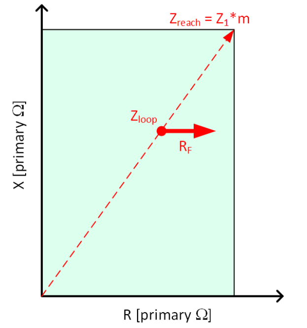
Figure 1: Distance Relay Characteristic in OpenDSS
Figure 1 shows the rectangular tripping region of the OpenDSS distance relay on the RX diagram. The shape is not adjustable, and the implementation does not account for polarization or loading effects. Especially for ground faults, the fault resistance, RF, may become high enough to shift the apparent impedance outside of the tripping region.
The basic input parameters are the “line” sequence impedances, Z1 and Z0, with a reach multiplier, m. From phasor measurements Vφ and Iφ, the relay constructs loop impedances, Zloop [1]:
k0 = (Z0 - Z1)/3Z1
IR = IA + IB + IC
ZLOOP-AG=VA/(IA + k0IR)
ZLOOP-AB=(VA-VB)/(IA-IB)
There are usually six loop impedances, three for the ground loops and three for the phase-to-phase loops. See [1] for more background, including effects not implemented here.
The distance relay function works with other relay parameters, including reclose. The new ones are:
• Type should be input as “distance”
• Z1MAG and Z1ANG, the positive-sequence primary impedance in ohms and degrees.
• Z0MAG and Z0ANG, the zero-sequence primary impedance in ohms and degrees. The effect of this impedance is incorporated into k0.
• Mphase is the reach in per-unit of Z1MAG ∠ Z1ANG, used in Figure 1 for the three phase-to-phase loops.
• Mground is the reach in per-unit of Z1MAG ∠ Z1ANG, used in Figure 1 for the three phase-to-ground loops. By using k0, the ground reach can be expressed on the same base as phase reach.
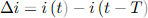
A test case is shown in Figure 2, where the line impedances per mile come from example 4.1 of [2]. The input file is DistanceRelayTest.dss on SourceForge [3]. The line impedances per mile define Z1 and Z0, so that Mphase and Mground become the desired reach in miles of line, rather than per-unit of the total impedance. The test case simulates 7 faults in a span of 1.2 seconds, run at time step of 0.01 seconds. Figure 3 shows the total source current, Iplotted in Figure 2, through the sequence of fault initiation, fault clearing and reclosing. The event log is provided in Table 1.
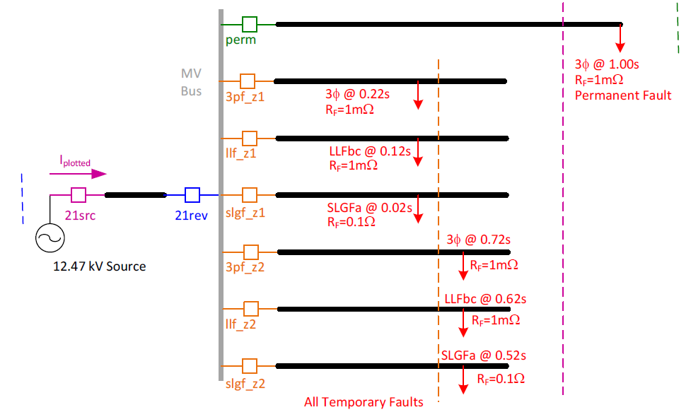
Figure 2: Test System for Distance Relays
Some notes of interpretation:
• The six individual feeder relays in orange are set to reach 1.4 miles. They detect, clear and reclose the three temporary faults that are 1.2 miles away, but not the three temporary faults that are 1.6 miles away. These relays have a tripping delay of 0.02 seconds.
• The source relay in magenta reaches 2.5 miles, but has a longer delay of 0.03 seconds. This relay trips the three faults not detected by the feeder relays. As shown in Figure 3, that set of three faults has lower currents than the first set. The gap between the two sets of faults allows the source relay time to reset, otherwise, it could lock out during the second set of three faults. The reset time for the source relay is 0.2 seconds.
- The source relay doesn’t trip for any of the first three faults, because its delay is longer than any of the feeder relays.
- The source relay doesn’t trip for the permanent fault because it’s out of reach.
• The seventh feeder relay in green reaches 3.5 miles. It’s the only one to detect the permanent three-phase fault at the end of the line, and trips four times to lockout between 1.0 and 1.2 seconds.
• The receiving end line relay in blue reaches 3.0 miles (not shown to scale) in the reverse direction from the faults. It detects none of them. The delay is 0.01 seconds, so if the directional determination failed, or the MonitoredTerminal changes from 2 to 1, it would trip.

Figure 3: Source current magnitudes during distance relay test sequence, step size=0.01 seconds
Incremental Distance
A time-domain or incremental version of distance protection, sometimes referred to as TD21, was originally developed decades ago as an option for ultra-high-voltage (UHV) transmission lines. In one available implementation [4, 5], the incremental voltage and current signals are derived from one-cycle memory waveforms. Many settings are the same as for conventional function 21. Other than speed, the TD21 function may be helpful with inverter-based sources that don’t generate much fault current. A time-domain model of this relay has been implemented to work with COMTRADE files, obtained from either transient simulation or field measurement.
A fast-phasor version of TD21 [6] is available for OpenDSS [7]. It requires Δt no more than one cycle, and preferably 1 millisecond. The relay operation of each loop is governed by:
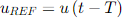
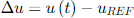


Where the six loop currents, i, six loop voltages, u, and six reach impedances, ZHSD, are defined the same way as for the regular distance function. The Δ quantities are obtained by looking back one cycle period, T, in the relay’s memory. Both real and imaginary parts of ZDIR must be greater than zero for the directional supervision to enable tripping. Then |uHSD|≥|uREF| is required for trip. In this formulation, i, v and the Δ quantities are all phasors, updated several times per cycle to approximate the time domain relay’s performance. For more accuracy, electromagnetic transient (EMT) simulation should be used with waveform processing in the time-domain relay model.
The simulation results from [7] are shown in Figure 4 and Table 2. The distance estimates are a little more accurate than in Table 1. On the other hand, when the perm relay recloses into a fault in Figure 4, the subsequent trips take longer than the first one. The memory buffer has to fill up after the reclose before the Δ quantities are valid. In setting up [7], the 21src relay uses the PhaseTrip parameter = 400, i.e., greater than the default 1.0, as a fault detection threshold. The current magnitude on at least one phase must exceed PhaseTrip to arm the TD21 logic. If all phase currents fall below PhaseTrip while the relay is armed to open, the relay drops out as necessary for zone coordination to work during the first set of three faults. It should suffice to set PhaseTrip above the highest expected load flow current.
Figure 4: Source current magnitudes during TD21 relay test sequence, step size=0.001 seconds
Table 1: Event Log for Distance Relay Test Case
Hour=0, Sec=0.03, ControlIter=1, Element=Fault.slgf_z1, Action=**APPLIED**
Hour=0, Sec=0.04, ControlIter=1, Element=Relay.slgf_z1, Action=OPENED ON 21 0.781 PU DIST G1
Hour=0, Sec=0.04, ControlIter=2, Element=Fault.slgf_z1, Action=**CLEARED**
Hour=0, Sec=0.06, ControlIter=1, Element=Relay.slgf_z1, Action=CLOSED
Hour=0, Sec=0.13, ControlIter=1, Element=Fault.llf_z1, Action=**APPLIED**
Hour=0, Sec=0.14, ControlIter=1, Element=Relay.llf_z1, Action=OPENED ON 21 0.735 PU DIST G2 G3 P23
Hour=0, Sec=0.14, ControlIter=2, Element=Fault.llf_z1, Action=**CLEARED**
Hour=0, Sec=0.16, ControlIter=1, Element=Relay.llf_z1, Action=CLOSED
Hour=0, Sec=0.22, ControlIter=1, Element=Fault.3pf_z1, Action=**APPLIED**
Hour=0, Sec=0.23, ControlIter=1, Element=Relay.3pf_z1, Action=OPENED ON 21 0.736 PU DIST G1 G2 G3 P12 P13 P23
Hour=0, Sec=0.23, ControlIter=2, Element=Fault.3pf_z1, Action=**CLEARED**
Hour=0, Sec=0.25, ControlIter=1, Element=Relay.3pf_z1, Action=CLOSED
Hour=0, Sec=0.26, ControlIter=1, Element=Relay.slgf_z1, Action=RESET
Hour=0, Sec=0.36, ControlIter=1, Element=Relay.llf_z1, Action=RESET
Hour=0, Sec=0.45, ControlIter=1, Element=Relay.3pf_z1, Action=RESET
Hour=0, Sec=0.52, ControlIter=1, Element=Fault.slgf_z2, Action=**APPLIED**
Hour=0, Sec=0.55, ControlIter=1, Element=Relay.21src, Action=OPENED ON 21 0.507 PU DIST G1
Hour=0, Sec=0.55, ControlIter=2, Element=Fault.slgf_z2, Action=**CLEARED**
Hour=0, Sec=0.57, ControlIter=1, Element=Relay.21src, Action=CLOSED
Hour=0, Sec=0.62, ControlIter=1, Element=Fault.llf_z2, Action=**APPLIED**
Hour=0, Sec=0.65, ControlIter=1, Element=Relay.21src, Action=OPENED ON 21 0.490 PU DIST G2 G3 P23
Hour=0, Sec=0.65, ControlIter=2, Element=Fault.llf_z2, Action=**CLEARED**
Hour=0, Sec=0.67, ControlIter=1, Element=Relay.21src, Action=CLOSED
Hour=0, Sec=0.72, ControlIter=1, Element=Fault.3pf_z2, Action=**APPLIED**
Hour=0, Sec=0.75, ControlIter=1, Element=Relay.21src, Action=OPENED ON 21 0.490 PU DIST G1 G2 G3 P12 P13 P23
Hour=0, Sec=0.75, ControlIter=2, Element=Fault.3pf_z2, Action=**CLEARED**
Hour=0, Sec=0.77, ControlIter=1, Element=Relay.21src, Action=CLOSED
Hour=0, Sec=0.95, ControlIter=1, Element=Relay.21src, Action=RESET
Hour=0, Sec=1, ControlIter=1, Element=Fault.perm, Action=**APPLIED**
Hour=0, Sec=1.01, ControlIter=1, Element=Relay.perm, Action=OPENED ON 21 0.735 PU DIST G1 G2 G3 P12 P13 P23
Hour=0, Sec=1.05, ControlIter=1, Element=Relay.perm, Action=CLOSED
Hour=0, Sec=1.06, ControlIter=1, Element=Relay.perm, Action=OPENED ON 21 0.735 PU DIST G1 G2 G3 P12 P13 P23
Hour=0, Sec=1.1, ControlIter=1, Element=Relay.perm, Action=CLOSED
Hour=0, Sec=1.11, ControlIter=1, Element=Relay.perm, Action=OPENED ON 21 0.735 PU DIST G1 G2 G3 P12 P13 P23
Hour=0, Sec=1.15, ControlIter=1, Element=Relay.perm, Action=CLOSED
Hour=0, Sec=1.16, ControlIter=1, Element=Relay.perm, Action=OPENED ON 21 0.735 PU DIST G1 G2 G3 P12 P13 P23 & LOCKED OUT
Table 2: Event Log for TD21 Relay Test Case
Hour=0, Sec=0.02, ControlIter=1, Element=Fault.slgf_z1, Action=**APPLIED**
Hour=0, Sec=0.03, ControlIter=1, Element=Relay.slgf_z1, Action=OPENED ON TD21 0.895 PU DIST G1
Hour=0, Sec=0.03, ControlIter=2, Element=Fault.slgf_z1, Action=**CLEARED**
Hour=0, Sec=0.12, ControlIter=1, Element=Fault.llf_z1, Action=**APPLIED**
Hour=0, Sec=0.13, ControlIter=1, Element=Relay.llf_z1, Action=OPENED ON TD21 0.897 PU DIST G2 G3 P23
Hour=0, Sec=0.13, ControlIter=2, Element=Fault.llf_z1, Action=**CLEARED**
Hour=0, Sec=0.22, ControlIter=1, Element=Fault.3pf_z1, Action=**APPLIED**
Hour=0, Sec=0.23, ControlIter=1, Element=Relay.3pf_z1, Action=OPENED ON TD21 0.899 PU DIST G1 G2 G3 P12 P13 P23
Hour=0, Sec=0.23, ControlIter=2, Element=Fault.3pf_z1, Action=**CLEARED**
Hour=0, Sec=0.52, ControlIter=1, Element=Fault.slgf_z2, Action=**APPLIED**
Hour=0, Sec=0.53, ControlIter=1, Element=Relay.slgf_z1, Action=CLOSED
Hour=0, Sec=0.55, ControlIter=1, Element=Relay.21src, Action=OPENED ON TD21 0.703 PU DIST G1
Hour=0, Sec=0.55, ControlIter=2, Element=Fault.slgf_z2, Action=**CLEARED**
Hour=0, Sec=0.57, ControlIter=1, Element=Relay.21src, Action=CLOSED
Hour=0, Sec=0.62, ControlIter=1, Element=Fault.llf_z2, Action=**APPLIED**
Hour=0, Sec=0.63, ControlIter=1, Element=Relay.llf_z1, Action=CLOSED
Hour=0, Sec=0.65, ControlIter=1, Element=Relay.21src, Action=OPENED ON TD21 0.706 PU DIST G3 P23
Hour=0, Sec=0.65, ControlIter=2, Element=Fault.llf_z2, Action=**CLEARED**
Hour=0, Sec=0.67, ControlIter=1, Element=Relay.21src, Action=CLOSED
Hour=0, Sec=0.72, ControlIter=1, Element=Fault.3pf_z2, Action=**APPLIED**
Hour=0, Sec=0.73, ControlIter=1, Element=Relay.3pf_z1, Action=CLOSED
Hour=0, Sec=0.75, ControlIter=1, Element=Relay.21src, Action=OPENED ON TD21 0.709 PU DIST G1 G2 G3 P12 P13 P23
Hour=0, Sec=0.75, ControlIter=2, Element=Fault.3pf_z2, Action=**CLEARED**
Hour=0, Sec=0.77, ControlIter=1, Element=Relay.21src, Action=CLOSED
Hour=0, Sec=0.967, ControlIter=1, Element=Relay.21src, Action=RESET
Hour=0, Sec=1, ControlIter=1, Element=Fault.perm, Action=**APPLIED**
Hour=0, Sec=1.011, ControlIter=1, Element=Relay.perm, Action=OPENED ON TD21 0.876 PU DIST G1 G2 G3 P12 P13 P23
Hour=0, Sec=1.051, ControlIter=1, Element=Relay.perm, Action=CLOSED
Hour=0, Sec=1.069, ControlIter=1, Element=Relay.perm, Action=OPENED ON TD21 0.876 PU DIST G1 G2 G3 P12 P13 P23
Hour=0, Sec=1.109, ControlIter=1, Element=Relay.perm, Action=CLOSED
Hour=0, Sec=1.127, ControlIter=1, Element=Relay.perm, Action=OPENED ON TD21 0.876 PU DIST G1 G2 G3 P12 P13 P23
Hour=0, Sec=1.167, ControlIter=1, Element=Relay.perm, Action=CLOSED
Hour=0, Sec=1.185, ControlIter=1, Element=Relay.perm, Action=OPENED ON TD21 0.876 PU DIST G1 G2 G3 P12 P13 P23 & LOCKED OUT
References
[1]. Schweitzer and Kasztenny, “Distance protection: Why have we started with a circle, does it matter, and what else is out there?”, 2018. https://doi.org/10.1109/CPRE.2018.8349791
[2]. W. H. Kersting, Distribution System Modeling and Analysis, 3rd Ed., CRC Press, 2016.
[3]. [online] https://sourceforge.net/p/electricdss/code/HEAD/tree/trunk/Test/DistanceRelayTest.DSS
[4]. Schweitzer et. al., “Speed of Line Protection – Can We Break Free of Phasor Limitations?”, 2015. https://doi.org/10.1109/CPRE.2015.7102184
[5]. Schweitzer et. al., “Performance of Time-Domain Line Protection Elements on Real-World Faults”, 2016. https://doi.org/10.1109/CPRE.2016.7914904
[6]. Dzienis et. al. “Analysis of High-Speed-Distance Protection”, 2011. https://doi.org/10.1109/APAP.2011.6180585
[7]. [online] https://sourceforge.net/p/electricdss/code/HEAD/tree/trunk/Test/TD21RelayTest.DSS
---
1 This material is based upon work supported by the U.S. Department of Energy’s Office of Energy Efficiency and Renewable Energy (EERE) under Solar Energy Technologies Office (SETO) Agreement Number 34233.