Storage
The storage element is essentially a generator that can be dispatched to either produce power (discharge) or consume power (charge) within its power rating and its stored energy capacity. The model was developed from the Generator element model. Thus, it has inherited some of the features such as a built-in energy meter and an interface to user-written DLLs.
A storage element can either act independently or be controlled by a StorageController element.

Figure 1. Basic concept of the Storage Element
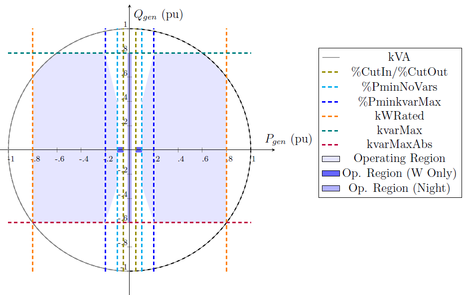
Figure 2. General Inverter Capability Curve
The model may be used in a Snapshot power flow mode to simply compute the power flow for a selected state of the Storage element flow control (see Figure 1). In that case, you would simply set the state to one of {IDLING | CHARGING | DISCHARGING} and then solve.
Note that there will only be power discharged if the present charge level (kWhStored or %Stored properties) is greater than the specified reserve level (see %Reserve property). The Storage element will only take charge when the kWhStored value is less than kWhRated. You can specify the rate of discharge with the %Discharge value and the rate of charge with the %Charge value.
However, the strength of the model is in time-varying simulation modes. Daily, Yearly, and DutyCycle modes are supported. You would typically use Daily or Yearly modes to look at general energy issues over a period of time with time step sizes of several minutes to one hour. The Dutycycle mode would be used to study the effectiveness of storage to compensate for short term power variations such as might occur in a matter of seconds with a cloud transient affecting solar PV generation.
The storage element can also produce or absorb reactive power (vars) within the kVA rating of the inverter. That is, a StorageController object requests a certain amount of kvar and the storage element provides it if the inverter has any capacity left. The storage element can produce/absorb vars while idling.
Losses are important when evaluating storage schemes. The model allows separate specification of charging and discharging efficiencies. The default values for each direction are 90%, making a nominal round trip efficiency of 81%. Set the charge and discharge efficiency to desired values.
In addition, idling losses may be specified. These represent energy required by the internal controls, heaters, coolers, etc., to maintain proper battery temperatures. This loss is currently specified as a single average value specified in percent of power rating (default = 1%) and is modeled as a constant impedance in shunt with the power system. Of course, your script can change this value on the fly.
In charging or discharging mode, the Storage element is generally modeled as a simple constant (P+jQ) model (model=1, the default). A constant Z model (model=2) is also available. The Usermodel support code was ported from the Generator model. This requires a DLL to be written.
The Storage element can operate either in standalone mode or be controlled by a StorageController [2], responsible for commanding its active power dispatch, and/or an InvControl [3], responsible for limiting its active power dispatch and/or requesting reactive power according to different functions.
The Storage model is developed based on the old Storage model, which in turn was originally de- veloped based on the Generator element model. Thus, both the new and the old Storage models have inherited some of the features from the Generator model such as a built-in energy meter and an interface to user-written DLLs.
The Storage element can be used in a Snapshot power flow to simply compute the power flow for a selected state of the Storage element. In that case, you would simply set the state and then solve. However, the strength of the model is in time-varying simulation modes. The model supports Daily, Yearly and DutyCycle modes. Daily or Yearly modes are intended for analyzing energy-related issues over a period of time with time step sizes from several minutes to one hour. DutyCycle mode is intended for studying the effectiveness of energy storage to compensate for short-term second-scale power variations, e.g., during cloud transients affecting solar PV generation.
As shown in Figure 1, the general Storage model is firstly presented and its operation in charging, discharging and idling states is explained. Next, different ways to manage energy storage dispatch are summarized. Then, all available standalone or “self-dispatch” modes are introduced and a summary of the Storage state variables is provided. Then, all “self-dispatch” are illustrated with several examples.
Dispatch Modes and Triggers
The user specifies the dispatch mode as one of
{DEFAULT | FOLLOW | EXTERNAL| LOADLEVEL | PRICE }
The ChargeTrigger and DischargeTrigger values interact differently in each mode. Basically, when a trigger level is surpassed the Storage element is permitted to go into the corresponding operating mode. Whether it actually does depends on several factors.
Default Mode: The triggers follow the specified load shape corresponding to the present solution mode (Daily, Yearly, Dutycycle). For example, if a Yearly solution is being performed, the storage device will discharge at the (fixed) specified discharge rate whenever the Yearly LoadShape object value exceeds the DischargeTrigger value. It will stay in Discharge mode until either the LoadShape value drops below the trigger level or the Storage element depletes its stored energy down to the reserve level. When the LoadShape value drops below the ChargeTrigger value, the Storage element will begin to charge at the specified charging rate. It will continue charging until the storage is built back up to 100% or another discharge cycle is required.
There is a default time for starting the charge cycle (TimeChargeTrigger) that will override the ChargeTrigger criterion if it specified. This is to ensure that Charging will take place even if the load level does not drop below the ChargeTrigger value at any time during the day. Set TimeChargeTrigger to a negative number to disable a default charging time.
For example, the default charging time is 2 AM. At this time, the Storage element will attempt to charge even if the load has not dropped below the ChargeTrigger value. This is a strategy for ensuring that the Storage element is always fully charged for the next day’s peak load.

Figure 3. Illustrating Default Dispatch
The default mode is illustrated in Figure 2. The Dischargetrigger property is set to 0.92 and the Chargetrigger property to 0.4. When the dispatch loadshape multiplier exceeds 0.92 in this case, the STORAGE element is set to discharge at the presently-defined discharge rate. Likewise, when the dispatch loadshape multiplier drops below 0.40, the charge cycle begins. On days when the loadshape multiplier does not drop below 0.40, the time charge, which defaults to 2 AM, takes and starts the charging at the designated rate.
FOLLOW mode: The kW and kvar output of the STORAGE element follows the active loadshape multipliers until kWh storage is either exhausted or full. The STORAGE element discharges for positive values and charges for negative values. Charging and discharging are proportional to the kWrated property. This is illustrated in Figure 3. The Discharge Cycle is set to nominally follow the shape of the daily peak that occurs approximately 5 PM. If you had a 1000 kWh battery with a 250 kW inverter. Over the 4.5 hr period, this would nearly discharge the battery, reaching a peak of 250 kW at 5 PM (hr 17). At 2 AM the next day, the charge cycle would begin at 2 AM ramping up to 250 kW over 0.5 hr and then continuing, if needed, until 6 AM. Obviously, you would have to simulate at least 2 days to see if this would work the way you wanted because the STORAGE unit begins fully charged. Therefore, there would be no charging on the first charge cycle.
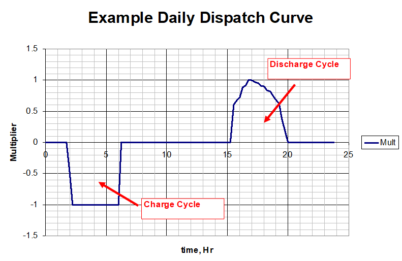
Figure 4. Example Daily Charge/Discharge Cycle in Follow Mode
Figure 4 shows a result that might come from the simulation described. The Loadshape in Figure 3 is overlayed on the Power at the terminals of the storage device. A positive value for power denotes discharging in this chart (OpenDSS will show the power as negative because it is coming out of the terminal.)
Note that the 1000 kWh battery discharges to the reserve level of 20% about one hour short of meeting the discharge dispatch goal. The specified charge cycle is a little longer than neeted to get the battery back to 100% charge level before charging is prohibited by following the dispatch loadshape.
You could use this daily shape for a yearly simulation. It would simply repeat over and over.
Note that there is no guarantee of charging in Follow mode. The loadshape must be defined negative for a period to force charging. You generally want somewhat more area under the charging curve than the discharge curve to compensate for losses.
If the STORAGE element has insufficient kWh to make it through the discharge cycle, it will switch to idling. Likewise, if the storage element fills before the end of the charge cycle, it will switch to idling. Charging and discharging losses are accounted for during these cycles.
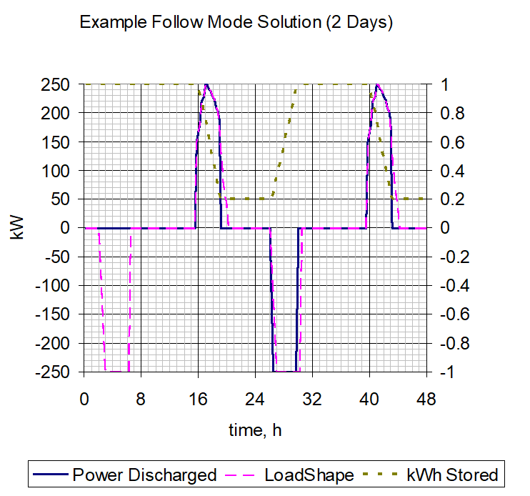
Figure 5. Example Simulation Result
Although not shown, both kW and kvar are dispatched. The kW is dispatched first and then the kvar is dispatched up to the kVA rating of the STORAGE element. As with all Loadshape objects, if Qmult is not specified, the reactive power multiplier defaults to the Mult property value (same as for kW).
The reactive power dispatch during simulations is relative to the value after the most recent setting of the kvar property, or the kW and PF properties. This establishes the base kvar value. The kvar output is determined by multiplying the Qmult value times the base kvar value.
The Loadshape objects used with this mode are usually Normalized to 1.0 or another per unit value.
The following script was used to generate the result shown in Figure 4:
Clear
New Circuit.TestStorage
~ BasekV=12.47
New Line.Line1 Bus1=Sourcebus LoadBus ! default line
New Loadshape.DailyShape npts=96 minterval=15 mult=[file=storagetestshape.csv]
New Storage.Battery phases=3 Bus1=loadbus kV=12.47 kW=250 kWrated=250 kWhrated=1000
~ dispmode=follow daily=dailyshape
set voltagebase=[12.47]
calcv
new monitor.PQ storage.battery 1 ppolar=no mode=1
new monitor.Vars storage.battery 1 mode=3
solve
solve mode=daily step=15m number=(2 96 *)
show mon PQ
show mon vars
(Note that the dispatch shape in Figure 3 was loaded into the file “storagetestshape.csv”.)
LOADLEVEL or PRICE mode:This DischargeTrigger/ChargeTrigger algorithm may also be applied to the global LOADLEVEL or PRICE values instead of the LoadShape objects defined for a particular Storage element.
See the Help for the following Options:
LOADLEVEL is set at a global circuit value with:
Set LoadMult= perunitvalue
Set DefaultDaily=MyDailyLoadShapeName (for daily-mode solutions)
Set DefaultYearly=MyYearlyLoadshapeName (for yearly mode solutions)
PRICE is set to a global circuit value with:
Set PriceSignal= value
Set PriceCurve= MyPriceCurveName
As of Ver. 7.4.1 build 35, price curves are defined with a PRICESHAPE object rather than a LoadShape object.
With any of the above three dispatch modes, you can get quite creative defining LoadShape objects in, for example, MS Excel that will allow for the simulation of a wide variety of charge/discharge behaviors. You can use this procedure to simulate the effect of having a central storage controller even if none is defined. By assigning the same loadshapes to a number of Storage elements, you can simulate many aspects of a StorageController handling a fleet of dispersed storage devices.
EXTERNAL mode: The Storage element does not attempt to determine its own state in this mode. Instead, it assumes a StorageController element will provide the required control of the state of the Storage element. This mode is automatically set when a StorageController grabs control of a Storage element.
While you can make up loadshapes to perform offline simulation of load following, etc. a StorageController is required to perform this function in real time simulations or off-line simulations that do not have predefined behaviors.
In addition to these dispatch modes, you may simply control the State of the Storage element explicitly by scripting the simulation through a script file or under program control through the COM interface.
Examples:
New storage.JO0235 phases=1 bus1=X_637.1 yearly=Phasealoadshape
~ kV=0.24 kwrated=25 pf=1.0 kwhrated=25
~ state=IDLING DischargeTrigger=0.8 ChargeTrigger=0.6
// 3-phase version
New Storage.Store1 phases=3 Bus1=LVBus kV=0.400 conn=Delta kVA=60
~ kWrated=60 kWHrated= 0.20833 %reserve=50
~ state=discharge
~ kW=50 PF=1
// 1-phase L-L connected version with dynamics DLL
New Storage.Store1 phases=1 Bus1=LVBus.1.2 kV=0.400 conn=delta kVA=60
~ kWrated=60 kWHrated= 0.20833 %reserve=50
~ state=discharge
~ kW=50 PF=1
// connect to user-written dynamics model
~ DynaDLL="C:\Users\prdu001\OpenDSS\Source\DESS1\Dess1.DLL"
~ DynaData=(file=DESSModel_Test.Txt)