TechNote OpenDSS Neutral Rules
OpenDSS Neutral Conventions
This document applies to the Rneut and Xneut properties of Load and Transformer elements. (It formerly applied to Generator elements, but those properties have been disabled.)
Wyeconnected Load and Transformer elements have an implicit neutral impedance that may be exploited, if desired. Figure 1 shows a schematic of the concept for a 1phase Load element. The same concept applies to multiphase wye (or star) connected Loads and Transformer windings.
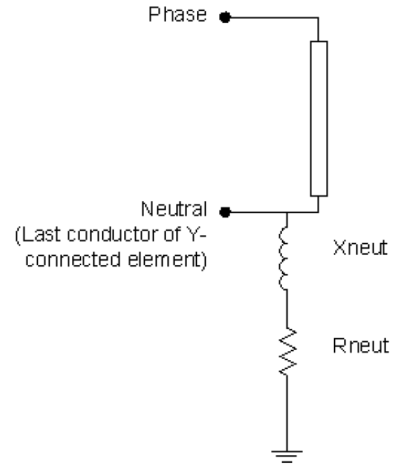
Figure 1. Schematic of a Load Element showing implicit neutral impedance.
Key features of the implicit neutral impedance are:
•The impedance is a series R + jX
• An nphase wyeconnected element has n+1 conductors on the wyeconnected terminal. The neutral impedance is connected between the last (n+1) conductor and ground (voltage reference). The default value of Rneut is 1.
• Since negative resistance is not physically realizable, this is used to signify to the OpenDSS that the neutral impedance is open, or infinite.
• Xneut may be defined as negative, although it is typically not and it may not work as expected.
• You may enter Rneut and Xneut as 0. The program replaces them with 1 microohm. However, if you want to connect the conductor solidly to ground, simply connect the neutral conductor to node 0 at the bus.
Rules
If you wish to use the implicit neutral impedance, be sure to explicitly specify the connection of the conductors. If you simply use the shorthand bus connection notation and take the default connection, the (n+1) conductor will be connected to node 0 and will be grounded. The neutral impedance will be shorted out.
Note that the neutral impedance will show up in the primitive Y matrix for the element (show Yprim) but that element in the matrix will never get added into the system Y matrix because of the connection to Node 0.
For example, consider the definition of a 3phase wye connected 200 kW Load (3 phases and wye connection are defaults for a Load element):
New Load.MyLoad bus1=MyBus kW=200 pf=.95 rneut=100
This is shorthand for (note the bus connection):
New Load.MyLoad bus1=MyBus.1.2.3.0 kW=200 pf=.95 rneut=100
Despite the fact that Rneut is declared to be >0, the default connection ends up shorting it out. Assuming node 4 is to be used for the neutral connection, the correct way to define this load is:
New Load.MyLoad bus1=MyBus.1.2.3.4 kW=200 pf=.95 rneut=100
This allows the neutral to float above ground depending on the current in the implicit neutral impedance and on any other connections to Node 4 of MyBus.
•The current in the implicit neutral branch is not directly visible, although may be seen in the Show Currents Elem Resid report as the residual current. The current shown for the neutral conductor is not the same current. It would be zero if nothing else is connected to Node 4.
•The voltage reported for Node 4 is the neutral-to-earth voltage.
External Neutral Reactor
Many users prefer to ignore the implicit neutral impedance and use a 1phase Reactor element for the neutral impedance. This increases the amount of scripting (you have to define a new element) but does not increase the number of nodes. Therefore, the impact on solution speed is minimal.
For example, the following definition with a separate 100ohm neutral resistor is equivalent to the last example above:
New Load.MyLoad bus1=MyBus.1.2.3.4 kW=200 pf=.95 ! No Rneut
New Reactor.MyNeutReactor phases=1 bus1=MyBus.4 R=100 X=0
Note that like a Capacitor, the second terminal of a Reactor defaults to MyBus.0, which results in a grounded wye connection. So there is no need to explicitly specify it if that is what you want.
Potential advantages of using a Reactor element to implement the neutral grounding impedance of a Load or Transformer include:
•The currents in the neutral reactors are explicitly reported in the usual current Show or Export reports. This may make it easier to postprocess if there is a need.
•The neutral reactors can be parallel RX as well as series RX, which will have a different frequency response.
•Possibly less likely to make a connection error.
For Generator objects, the internal neutral has been disabled. A separate Reactor element must be used to provide a neutral impedance. Note: neutral impedances in Generator objects will sometimes make the power flow fail to converge because the neutral voltage never converges satisfactorily. As a workaround, it is recommended to insert a 1:1 YDelta transformer in series with the Generator with appropriate impedances. The Generator is defined as connected in Delta and connected to the Delta side of the transformer. The neutral reactor is placed in the neutral on the Y side of the transformer. This arrangement generally works quite well over a wide range of neutral impedance values.