The Normal Solution method
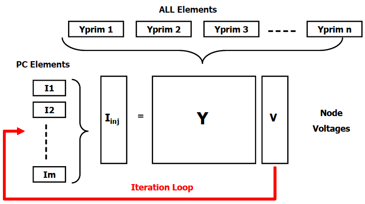
Figure 1 illustrates how the DSS puts all the PD elements and PC elements together to perform a solution.

Figure 1. OpenDSS Solution Loop
OpenDSS uses a fairly standard Nodal Admittance formulation of the circuit model that can be found documented in many basic power system analysis texts. Most electrical engineers have encountered nodal admittance formulations very early in their education. OpenDSS provides algorithms that build the nodal admittance matrices for common power distribution system elements from the data commonly available to power distribution engineers.
A primitive admittance matrix, Yprim, is computed for each circuit element in the model. These small nodal admittance matrices are used to construct the main system admittance matrix, Ysystem, that knits the circuit model together. Basically, the upper structure of the OpenDSS (the part that is written in Delphi) manages the creation and modification of the Yprim matrices for each element in the circuit as well as managing the bus lists, the collection of results through Meter elements, and the execution of Control elements. The Yprim matrices are fed to the sparse matrix solver, which constructs the system Y matrix.
An initial guess at the voltages, V, is obtained by performing a direct solution of I=YV. Loads and generators are modeled by their linear equivalents with no injection currents. This gets all the phase angles and voltage magnitudes in the proper relationship. This is somewhat analogous to a “flat start” in other power flow algorithms except that it takes into account all the connections of the multi-phase, multi-voltage level system. The resulting voltages are often quite close to the final converged solution including the nonlinear elements. This is important because the OpenDSS is designed to solve arbitrary n-phase networks in which there can be all sorts of transformer ratios and connections and it must have a good initial guess at the voltages.
The iteration cycle begins by obtaining the injection currents from all the power conversion (PC) elements in the system and adding them into the appropriate slot in the Iinj vector in the above figure. The sparse set is then solved for the next guess at the voltages. The cycle repeats until the voltages converge to typically 0.0001 pu.
The solution is mainly focused on solving the nonlinear system admittance equation of the form:

Where,
 compensation, or injection, currents from Power Conversion (PC) elements in the circuit, which may be nonlinear elements
The currents injected into the circuit from the PC elements, Iinj(V), are a function of voltage as indicated and basically represent the nonlinear portion of the currents from Load, Generator, PVsystem, and Storage elements in the circuit. Each PC element is queried in each iteration to provide its updated injection currents based on the present guess at the voltages. This process has the advantage of allowing considerable freedom in expressing the nonlinear behavior of the PC element. Thus, there are many load models and generator models.
There are a number of ways this set of nonlinear equations could be solved. The most popular way in OpenDSS is a simple fixed point method that can be written concisely:

 Until Converged
In words, after building Ysystem, start with a guess at the system voltage vector, V0, and compute the compensation currents from each PC element to populate the Iinj vector. Using a sparse matrix solver, compute the new estimate of Vn+1. Repeat this process until a convergence criterion is met.
The system Y matrix is typically not rebuilt during this process so the iterations go quickly. Refactorization of Y is not necessary as long as the elements are close to the actual value. This may result in a few extra iterations to reach a converged solution, but such iterations are computationally cheap in comparison to refactoring the large Y matrix.
This simple iterative solution has been found to converge quite well for most distribution systems that have adequate capacity to serve the load. The key is to have a dominant bulk power source, which is the case for most distribution systems. In the DSS, this is the “Normal” solution algorithm. There is also a “Newton” algorithm for more difficult systems (not to be confused with the typical Newton-Raphson power flow method).
When performing Daily or Yearly simulations, the solution at the present time step is used as the starting point for the solution at the next time step. Unless there is a large change in load, the solution will typically converge in 2 iterations – one to do the solution and one to check it to make sure it is converged. Thus, the DSS is able to perform such calculations quite efficiently. In fact, it has been found that the first guess at the next time step when the time step size is small is often good enough. The MinIterations option has been added to allow the user to override the default value of 2 iterations and the minimum number of iterations may be set to 1 for simulations such as Quasi-Static Time Series (QSTS) simulations at 1-s intervals. The program determines if the solution is good enough by comparing to the previous solution. Additional iterations will be executed automatically, if needed, to converge better. This can save almost half the computational effort in very long simulations at a small time step.
Control iterations are performed outside this loop. That is, a converged solution is achieved before checking to see if control actions are required. Then the control actions are executed without advancing time until there are no more control actions queued up. The time delay specified for each control dictates which controls operate.
