WindGen
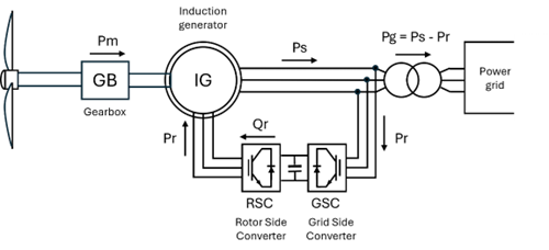
The Wind turbine model developed in previous stages of the project corresponds to a doubly fed induction generator (DFIG) like the one shown in Figure 1 [1-4]. This model considers the power exchange between the mechanical and electrical parts of a wind turbine. Among the features of the turbine that determine the performance of the generator there are the number of pole pairs for the generator, the gearbox ratio, wind speed, and the rotor radius among other parameters, which can be defined when declaring the model in OpenDSS.

Figure 1. DFIG wind power generator.
Steady state and QSTS model
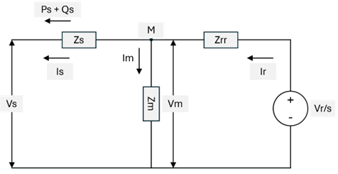
The model for steady state and QSTS model is based on the work presented by other authors in which the performance of the wind generator is given by the wind speed and the mechanical features of the device [5]. The electrical relationship of this model and its mechanical construction for steady state simulation has been proposed as shown in Figure 2. This electric equivalent allows to identify the electric variables to consider during the simulation based on the intrinsic impedances within the device.

Figure 2. Electrical equivalent for wind turbine model
The impedances proposed in Figure 2 correspond to the stator (Zs), rotor (Zrr) and magnetic core (Zm) given by the following expressions:


Where the R and X elements correspond to the resistance and reactance of each impedance. s is the generator slip based on the generator tip speed ratio and the performance coefficient. Based on Figure 1 and Figure 2 the active and reactive powers at the stator can be defined as:

This way and according to the simplifications proposed in [1, 4] the power generated can be generalized as follows:

Where Pm is the mechanical power generated by the wind turbine. The generator losses are entered into the model in the form of a curve that allows better to model the losses when the electric components here proposed are insufficient. The losses curve is a curve that interpolates the losses in percentage versus the wind speed. An example of a losses curve is shown at Figure 3. This curve can be defined using an XY curve object in OpenDSS.

Figure 3. Losses curve to be defined for modeling wind turbine in OpenDSS
The mechanical power in the model is given by the following expression:

Where:
|
Symbol |
Description |
Units |
|
ρ |
Air density |
kg/m3 |
|
A |
Rotor area (πR2) |
R is the rotor radius in meters |
|
Vw |
Wind speed |
m/s |
|
Cp |
Turbine performance coefficient |
N/A[1] |
The performance coefficient depends on the manufacturer specifications as indicated in [4, 5]. The induction generator slip can be then calculated with the following expressions:

Where:
|
Symbol |
Description |
Units |
|
Ρ |
Number of pole pairs of the induction generator |
N/A |
|
λ |
Tip speed ratio |
N/A |
|
fs |
Power system frequency |
Hz |
|
ag |
Gearbox ratio |
N/A |
With these parameters and expressions, the power delivered by the wind turbine can be calculated at each simulation step.
[1] N/A = Not applicable
