3-Phase Transformer Modeling
3-phase Transformer Core Modeling
BackGround
This is a supplement to “Modeling Transformer Core Effects in OpenDSS” written in January 2010 and included with OpenDSS documentation. Refer to that document for more information, particularly for 3-legged core modeling
The present Transformer model in OpenDSS assumes no magnetic coupling between the phases. Coupling between phases is accomplished by electrical connections of the windings or by adding special circuits. You can approximate the magnetizing impedance of uncoupled cores simply by specifying the %imag property of the Transformer object. This is a linear model (constant inductance).
For most problems you will study with OpenDSS, transformer core modeling is not a significant issue. But you may encounter exceptions to this guideline. For example, we have recently been asked to look at some open-conductor fault cases with various types of 3-phase transformers. The different core designs react differently to this case so it is important to have a reasonable representation of the effects of the core design. In this document, we will discuss how to model the following core designs:
1. Shell-form designs
2. Core-form designs
3. 5-legged Core designs
Shell-Form Designs (and Triplex Cores and 3-phase Banks)
A 3-phase shell-form design is depicted in Figure 1. Each of the 3-phases is completely surrounded by core steel such that behaves nearly like 3 independent cores. It can be assumed for the purposes of most problems for which OpenDSS would be used that each phase is independent.
This is the default OpenDSS Transformer element model. No coupling between phases is represented. So you don’t have to do anything special to model Shell-form 3-phase transformers.
Shell-form transformers are generally very large: > 200 MVA. They are often preferred for large GSUs and transmission substations because they are generally more durable with respect to through-fault withstand.
On distribution systems, you will find two types of 3-phase transformers that can be modeled by the default Transformer model without modifications:
• Triplex core transformers: These are 3-phase transformers that consist of 3 independent 1-phase transformers mounted in the same tank. These transformers are often specified by utilities that have had problems with ferro-resonance with 5- legged core Yg-Yg transformers and still want to use the Yg-Yg connection.
• 3-phase banks: These are three independent 1-phase transformers, typically pole-mounted. They are very common in North American distribution systems on overhead lines. There is no magnetic coupling between the phases.

Figure 1. Typical 3-Phase Shell-form Transformer Designs (Mitsubishi Electric)
Core-Form Designs (3-legged)
The majority (>90%) of 3-phase utility distribution substation transformers 5 MVA, or greater, are core-form transformers (3-legged core designs – sometimes called “E” cores). The windings for each phase are installed over the three legs as depicted in Figure 2.
The electrical behavior that sets this design apart from other designs is that it behaves as if it has a delta-connected winding even if one is not physically present. This is called a “phantom tertiary” winding. The reason for this is depicted in Figure 2. There is no return path for zero-sequence flux totally within the core steel. The return flux path is through the insulating medium, which is some combination of oil, paper, air and, possibly, other gases. This path has low permeability (typically μr=1) and, therefore, higher reluctance, than the core steel. So the zero-sequence magnetizing reactance is substantially lower than the positive-sequence magnetizing impedance for which the flux stays in the core steel.
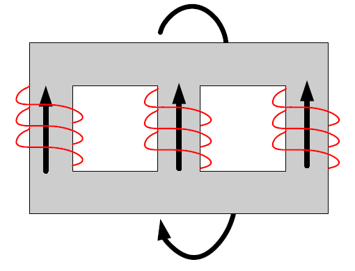
Figure 2. 3-phase Core-form Transformer Design Showing Zero-sequence Flux Paths
It is easy to model this in OpenDSS. You simply add a Delta winding to the transformer model. If it already has a Delta winding, you have the option of reducing the impedance to the existing Delta winding or adding another Delta winding.
The leakage reactance to the equivalent Phantom tertiary is usually fairly high on the transformer’s MVA base. Assuming you have an existing 2-winding transformer, add a 3rd winding connected in Delta. Set the initial guess for the percent reactances to the phantom tertiary to the following:
XHT = 100
XLT = 80
XHT is generally higher because the HV winding is usually wound at a larger radius than the LV and encompasses more area – therefore, more flux.
These values are frequently good enough if you have no other data. If you have zero-sequence test data available, you can compute the values needed to provide that. Note that in OpenDSS you can easily apply a 1-phase fault to the load side of the transformer and adjust the values to give the expected results.
You can also excite the transformer with a zero-sequence source (VSOURCE and ISOURCE can be set to provide a zero-sequence quantity – or just define a 1-phase source and tie all three phases of the transformer together and connect them to the source). There’s more than one way to “skin a cat”. (I take no ownership of that expression; just repeating it.)
In some cases, it would be sufficiently accurate to add a separate YgD transformer to one side of the existing transformer model. The impedance of the transformer would be adjusted to achieve the desired net zero-sequence impedance.
Refer to the “Modeling Transformer Core Effects in OpenDSS” for more detailed explanations for modeling 3-legged core-form transformers with various winding configurations.
5-Legged Core Designs
Many 3-phase padmount transformers in underground systems as well as platfom-mounted transformers in overhead systems are 5-legged core design.
The core may be a stacked core design or it may consist of 4 wound cores, each with a cross-section area to carry half the flux (Figure 3).
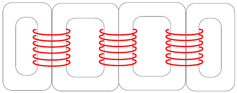
Figure 3. 5-Legged Core Design - Wound Cores
You can construct an approximate model of a 5-legged core transformer that is sufficient for most steady state applications with the model shown in Figure 4. This rather unusual-looking circuit forces the fluxes to sum as they would in the transformer. Each of the 4 reactors nominally represents one of the wound cores.
Referring to Figure 3, it should be obvious the two inner cores have a longer magnetic path than the two outer cores. At the same permeability, that means the inner cores have a higher reluctance than the outer cores, or a lower inductance. In a typical transformer the difference in length is approximately 20%.
To represent the 5-legged core in a state of low excitation, you could set Linner about 80% of Louter. This will yield a lower flux level on the outer cores, which shows up as a lower voltage across the Louter reactors. The flux in the inner cores will be approximately 30% higher than in the outer cores, which agrees with measured values such as those in “Flux Distribution Analysis in Three-Phase Si-Fe Wound Transformer Cores” by George Loizos, et. al., IEEE Transactions On Magnetics, Vol. 46, NO. 2, February 2010.
As the excitation level increases toward a typical design level of 1.7 T, the permeability of the inner cores decreases as the flux moves higher on the saturation curve. The flux in all cores eventually levels off at nearly the same value. The equivalent value of Linner in an OpenDSS model must decline farther relative to Louter to represent this. The equivalent value of Linner at full excitation is generally in the neighborhood of 50-60% of Louter. You
can experiment with the proportions to achieve the effect you want.
Keep in mind that you never will be able to model this exactly with a linear model in the phasor domain. But you can come close enough for many applications that need core behavior modeled.

Figure 4. Model for Representing Basic 5-legged Core Behavior in OpenDSS
The example OpenDSS script below demonstrates one way of modeling a 5-legged core transformer as shown in Figure 4. The core model is attached to the 4.16 kV LV winding. Thus, it consists of 3 low-impedance 1-phase transformers, each rated 2.4 kV and connected line-to-ground. The transformer impedance is 0.01 + j0.1% on a 25 MVA base, so it is reasonably close to ideal.
The secondaries of the transformers are connected in series: nodes 1..2, 2..3, and then 3..4. Note that the X value of the 4 reactors named 5LegMag_1 .. 5LegMag_4 is computed with OpenDSS in-line math. You may adjust the multiplier on the inner legs to achieve the desired split in the flux from inner to outer legs. If you want an even distribution of flux (represented by the voltage across the reactor), you will have to change the multiplier from 0.8 to about 0.5.
The base value for the reactance, X, was chosen to achieve approximately 0.2% magnetizing current.
Example Script for 5-Legged Core Model
Clear
New Circuit.5Leg
~ Bus1=MainBus BasekV=230 pu=1.0 Isc3=15000 Isc1=17000 X1R1=30 X0R0=30
New Reactor.YY5legLink Phases=3 Bus1=mainBus.1.2.3 Bus2=YY5legPri.1.2.3 R=0 X=0.001
New Transformer.YY5Leg XHL=10
~ Buses=[YY5legPri.1.2.3.0 YY5legBus.1.2.3.4]
~ kVs=[230 4.16]
~ conns=[wye wye]
~ kvas=[25000 25000] %LoadLoss=0.2
// Neutral Resistor
New Reactor.Rneut5YY Phases=1 bus1=YY5LegBus.4 Bus2=YY5LegBus.0 R=20 X=0
// 3 low-impedance 1-phase transformers for 5-legged core model
New XfmrCode.1phase Phases=1 XHL=0.1 %Loadloss=0.01 kvs=[2.4 2.4] kVAs=[25000 25000]
~ %imag=0 %noload=0
New Transformer.5legPh1 xfmrcode=1phase buses=[YY5LegBus.1.0 YY5legmagBus.1.2]
~ %imag=0 %noload=0
New Transformer.5legPh2 xfmrcode=1phase buses=[YY5LegBus.2.0 YY5legmagBus.2.3]
~ %imag=0 %noload=0
New Transformer.5legPh3 xfmrcode=1phase buses=[YY5LegBus.3.0 YY5legmagBus.3.4]
~ %imag=0 %noload=0
/***************
5-leg core magnetizing reactors (4)
Middle two legs have a higher reluctance than the outside two because the path is longer
This translates to lower inductance. In unsaturated state, length is about 20% longer
so X is about 80% of X in outside two legs. This results in lower Flux/voltage in
outside legs.
As flux density increases, X in middle legs will reduce until fluxes (voltages) about
the same.
****************/
New REACTOR.5LegMag_1 Phases=1 Bus1=YY5legmagBus.1 Bus2=YY5legmagBus.0 R = 0
~ X=(6969.6 1.0 *)
New REACTOR.5LegMag_2 Phases=1 Bus1=YY5legmagBus.2 Bus2=YY5legmagBus.0 R = 0
~ X=(6969.6 .8 *) ! set to 0.5 - 0.6 to balance fluxes
New REACTOR.5LegMag_3 Phases=1 Bus1=YY5legmagBus.3 Bus2=YY5legmagBus.0 R = 0
~ X=(6969.6 .8 *) ! set to 0.5 - 0.6 to balance fluxes
New REACTOR.5LegMag_4 Phases=1 Bus1=YY5legmagBus.4 Bus2=YY5legmagBus.0 R = 0
~ X=(6969.6 1.0 *)
Set voltagebases=[ 230 13.2 4.16]
Calcvoltagebases
Set Case=5Leg_Closed
Solve
Show voltage LN Node
Show Current elem Residual=y