Calculation of the monitored voltage in Volts
The voltages sampled by InvControl can be the nodal voltages of the controlled element or line-to-line and/or line-to-ground voltages of monitored bus or buses.
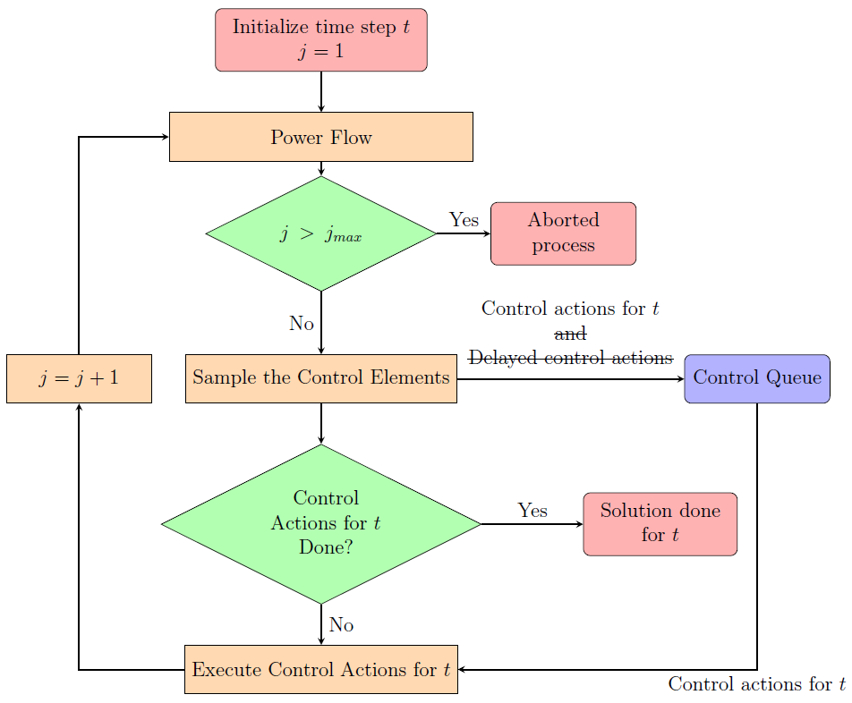
Figure 8: Block diagram of the control loop when only InvControl elements are considered
By default the InvControl samples the nodal voltages of the controlled element. For example, for a three-phase element, the voltages monitored in V can be written according to Equation 29.

In order to sample voltages of monitored bus or buses, the monBus and monBusesVbase properties of InvControl must be used. The monBus property stores the monitored buses and their nodes defined in a list and the monBusesVbase property stores the list with the corresponding base voltages for each of these monitored buses. For instance, Equation 30 shows the list with two monitored voltages (resulted from power flow) and Equation 31 the list with their respective base voltages.


Where:
- VmonBusA1 [t]j corresponds to the line-to-ground voltage of the node 1 of the bus A;
- VmonBusB12 [t]j corresponds to the line-to-line voltage between the nodes 1 and 2 of the bus B.
The values of the voltages of Equation 30 can present base voltages with distinct values and therefore, this list must have its values corrected to the same base voltage, which correspond to the rated voltage of the controlled element, as presented in Equation 32. This is necessary so that the calculation of the monitored voltage in V is made considering voltages of the same order of magnitude.

Where:
- Velementbase corresponds to the rated voltage of the controlled element which is the kV property value of the PVSystem.
A unique monitored voltage in V is calculated from one of the two lists present in Equations 29 or 32. The options for this selection are present in the monVoltageCalc property and are applied in the list to calculate the maximum, minimum or average value, according to the options described below:
- For AVG, the average monitored voltage is calculated by applying the mean in the list;
- For MAX, the monitored voltage is the maximum value present in the list;
- For MIN, the monitored voltage is the minimum value present in the list.
Thus, as a result, the monitored voltage in V is defined as Vmon[t]j.