Checking auxiliary options
The auxiliary options that can be selected are intended to limit the variations of the active power limit and/or the desired reactive power during time steps. As a result of this verification, pLopc[t]j and qDopc[t]j are defined.
Standard The standard option (default) does not limit the variation of the active power limit and the desired reactive power, as can be seen in the Equation 62 and Equation 63.


In this version of the model, the watt-pf and watt-var functions do not have the auxiliary options implemented. Therefore, the Equation 62 and Equation 63 are applied.
LPF This option consists of applying the active power limit, pLfun[t]j, and/or the desired reactive power, qDfun[t]j, as input of a first-order low pass filter with time constant equal to τ . As a result, the values of the options are set according to Equations 64 and 65. These equations present as initial conditions the results of these equations in the previous time step, pLopc[t − 1] and qDopc[t − 1].


Where τ is the value set in the LPFTau property.
RF This option limits the change of the active power limit and the desired reactive power between time steps to a maximum value. Equations 66 and 67 present the application of this option.

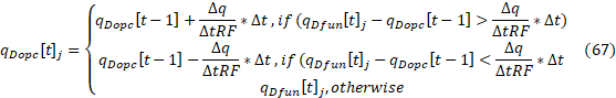
Where:
- Δp/ΔtRF and Δq/ΔtRF are the value set in the RiseFallLimit property;
- ∆t is the stepsize of the QSTS simulation. In other words, it corresponds to the difference between two consecutive time steps, t and t − 1, in a time scale.