Examples
All examples utilize the IEEE 8500-Node Test Feeder. This circuit is available in OpenDSS installation folder and should be located in “C : \ProgramFiles\OpenDSS\IEEETestCases\8500 − Node” if the standard installation procedure has been used. Furthermore, all modifications and scripts run to generate each example are also available in OpenDSS “Examples\StorageController− TechNote ” folder.
The base script for all cases is shown below. The unbalanced version of the circuit is considered, which is compiled through “Master-unbal.dss” file. The regulators and capacitor controllers originally present have been disabled to avoid any undesired discrepancies between the operation of the StorageController under different settings. A power monitor named m1 PQ has been placed at the feeder head. In most cases, the controller will also be monitoring powers and currents at this same location. Additionally, a loadshape has been specified and assigned to all loads of the circuit through batchedit command. Seven 3-phase storage elements with the same efficiency curve have been randomly allocated at the MV level of the feeder, Figure 8. Note that not all storage elements have the same power and energy capacities. The initial state of charge of all elements has been set to 70% such that there is some energy capacity available for charging the fleet at the beginning of the day. The operation of each storage element is recorded through a monitor in mode 3.
Any other code snippets used to run each example will be shown in the respective subsection.
!Compile Circuit and add loadshapes to all loads
Compile Master-unbal.dss !FromIEEE8500Buses Test Case Folder BatchEditCapControl..* enabled=False
BatchEdit RegControl..* enabled=False
New Monitor.m1 PQLine.ln5815900-1 terminal=1 mode=1 ppolar=No
New LoadShape.loadsloadshape interval=0 npts=24 csvfile=[LoadShape1.csv]
BatchEdit Load..* daily=loadsloadshape
!Inverter Efficiency Curve
New XYCurve.Eff npts=4 xarray=[.1 .2 .4 1.0] yarray=[.86 .9 .93 .97]
!Storagefleet
New Storage.A phases=3 bus1=l3235258 kv=12.47 %idlingkW=1
~ kWhrated=500.0 %stored=70 kWrated=100.0 EffCurve=Eff vminpu=0.8 vmaxpu=1.2
New Storage.B phases=3 bus1=m1069483 kv=12.47 %idlingkW=1
~ kWhrated=1000.0 %stored=70 kWrated=200.0 EffCurve=Eff vminpu=0.8 vmaxpu=1.2
New Storage.C phases=3 bus1=p862322 kv=12.47 %idlingkW=1
~ kWhrated=1650.0 %stored=70 kWrated=350.0 EffCurve=Eff vminpu=0.8 vmaxpu=1.2
New Storage.D phases=3 bus1=m1047615 kv=12.47 %idlingkW=1
~ kWhrated=1250.0 %stored=70 kWrated=300.0 EffCurve=Eff vminpu=0.8 vmaxpu=1.2
New Storage.E phases=3 bus1=m1069556 kv=12.47 %idlingkW=1
~ kWhrated=500.0 %stored=70 kWrated=150.0 EffCurve=Eff vminpu=0.8 vmaxpu=1.2
New Storage.F phases=3 bus1=l2688692 kv=12.47 %idlingkW=1
~ kWhrated=1200.0 %stored=70 kWrated=200.0 EffCurve=Eff vminpu=0.8 vmaxpu=1.2
New Storage.G phases=3 bus1=m1089131 kv=12.47 %idlingkW=1
~ kWhrated=1250.0 %stored=70 kWrated=250.0 EffCurve=Eff vminpu=0.8 vmaxpu=1.2
New Monitor.storageAstates element=Storage.A mode=3
New Monitor.storageBstates element=Storage.B mode=3
New Monitor.storageCstates element=Storage.C mode=3
New Monitor.storageDstates element=Storage.D mode=3
New Monitor.storageEstates element=Storage.E mode=3
New Monitor.storageFstates element=Storage.F mode=3
New Monitor.storageGstates element=Storage.G mode=3
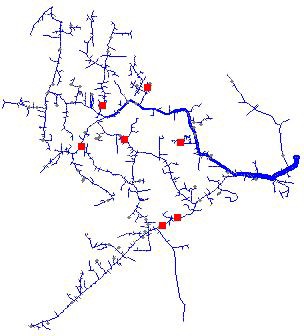
Figure 8: IEEE 8500 buses test case with location of storage fleet