Modeling Single-phase, Center-tapped Distribution Transformers
Modeling Single-phase, Center-tapped, Distribution Transformers
The question frequently arises concerning how to model the typical USstyle single-phase distribution transformer with a 120/240V secondary. Since there is no special transformer model in the DSS for this device, it is constructed using a single-phase transformer with three windings (this is physically what the transformer is). The schematic of the model is as shown in the figure below.
First, note the polarities of the windings. The usual error is to not properly connect Winding 3. It must be connected between Node 0
of Bus2 and Node 2, in that order.
This transformer may be modeled by the following scripts. The first script is for a Line-to-neutral connected transformer on Phase 1; the
second is a LinetoLine connected transformer between phases 1 and 2.
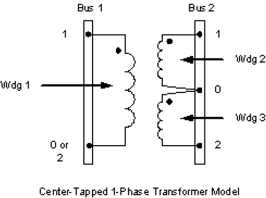
3-Winding Transformer Model
! LinetoNeutral Connected 1phase Centertapped transformer
New Transformer.Example1ph phases=1 Windings=3<br>
~ Xhl=2.04 Xht=2.04 Xlt=1.36 %noloadloss=.2<br>
~ Buses=[bus1.1 bus2.1.0 bus2.0.2] !!! Note polarity<br>
~ kVs=[7.2 .12 .12] ! ratings of windings<br>
~ kVAs=[25 25 25]<br>
~ %Rs = [0.6 1.2 1.2]<br>
~ conns=[wye wye wye] ! default
! LinetoLine Connected 1phase Centertapped transformer
New Transformer.Example1ph phases=1 Windings=3<br>
~ Xhl=2.04 Xht=2.04 Xlt=1.36 %noloadloss=.2<br>
~ Buses=[bus1.1.2 bus2.1.0 bus2.0.2] !!! Note polarity<br>
~ kVs=[12.47 .12 .12] ! ratings of windings<br>
~ kVAs=[25 25 25]<br>
~ %Rs = [0.6 1.2 1.2]<br>
~ conns=[delta wye wye]
Note that the winding voltage ratings are defined on the actual coil rating.
The next point of confusion is what to assume for the impedances of the 3winding transformer and the winding resistances. Some errors often occur when users attempt to take the default values. Some recommendations:
• Do not take the default shortcircuit reactance values; the default values are designed for a typical large power transformer that has 3 windings, such as a YYD connection. The impedances to the 3rd winding are too large (30 and 35%) for a typical distribution transformer. Use the values in the example if you don’t know exactly what they are.
• Do not use “%loadloss=…” to set the winding resistances. This property sets only windings 1 and 2. Explicitly set the winding resistances to avoid confusion.
The impedance in the example above more closely represent a Core form, interlaced connection (see the figure below from Tom Short’s book). Note that the LV windings are close together and are inside the HV winding. Short circuit reactance is a function of the spacing between the windings. The greater the spacing, the higher the reactance. In Shell form designs, one LV winding is wound outside the HV winding while the other is inside. Therefore, the impedance between the two low voltage windings (XLT=) is likely higher than the percent impedance between either one of the LV windings to the HV winding. In both cases, the typical HVLV impedance with be on the order of 23% for most distribution transformers.

Common distribution
transformer winding
constructions.