Operation
This section demonstrates the power flow and losses within the element during the operation in each of the three possible states.
The power flow within the Storage element is performed from the interface with the grid to the ideal storage component. First the active power at the interface with the grid, kW and kvar are determined. Then, all the losses (inverter, idling and charging/discharging losses) are subtracted, with the net effect of reducing the power that charges/discharges the ideal storage. The power flow within the Storage element is calculated identically in all OpenDSS solution modes (static, daily, yearly, duty) as described in the following subsections. The power flow within the Storage element at simulation time instant t is calculated based on the power at the Storage element grid interface obtained from the final power flow solution (power flow executed in the last control iteration) at simulation time instant t. For time-varying simulations, OpenDSS assumes this flow is constant over the time interval until next time instant t +∆t, where ∆t is the time step size selected. The following nomenclature is used:
- Pin[t]: power flowing into the storage at t when it is either in charging or idling states;
- Pout[t]: power flowing out of the storage or into the grid at t when it is in discharging state;
- Pidl: constant idling losses;
- ηinv[t]: inverter efficiency at t;
- ηch: charging efficiency;
- ηdch: discharging efficiency;
- E[t]: energy stored at t;
1.1 Charging state
The Storage element can only enter into charging state if the amount of energy stored, kWhStored, is less than the rated storage capacity, kWhRated. The rate of charge can be defined through either properties kW (as a negative value) or %Charge (percentage of the kWRated). The power flow within the storage element during the charging state is illustrated in Figure 2.
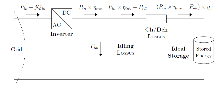
Figure 2. The Internal Power Flow of the Storage Element during Charging State
After the power Pin[t] at the storage element grid interface has been determined from the power flow solution1, the storage inverter losses are determined by:

The power at the DC side of the storage inverter, Pin[t] × ηinv[t], supplies the idling losses Pidl. The charging losses are calculated analogous to the storage inverter losses:

Thus, the total losses are:

and the power that effectively charges the ideal storage, Pch [t], is determined by

or, equivalently,

The energy stored at the next simulation time step, t + ∆t, is given by:

1.2 Discharging state
The Storage element can only enter into discharging state if the amount of energy stored is greater than the energy capacity to be held in reserve for normal operation, %Reserve × kWhrated. The discharge rate is defined either with kW (as a positive value) or %Discharge (percentage of the kWRated).
The power flow within the storage element during the discharging state is illustrated in Figure 3.
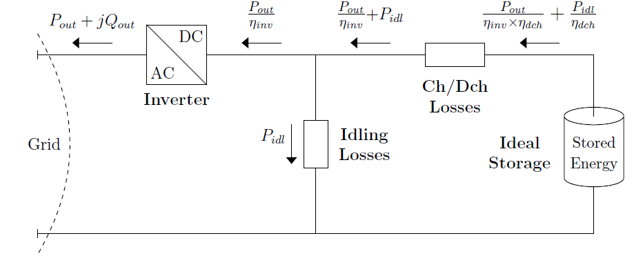
Figure 3. TheThe Internal Power Flow of the Storage Element during Discharging State
After the power flowing out of the Storage element, Pout[t] has been determined from the power flow solution2, the storage inverter losses are determined by:

The ideal storage supplies the power at the DC side of the inverter along with the idling losses and the discharging losses. The discharging losses are given by:

The total losses during discharging state are calculated with

and the power that effectively discharges the ideal storage, Pdch[t], is determined by

or,

Therefore, the energy stored at the following time step, t + ∆t, is given by:

1.3 Idling state
When the storage element is in idling state, the idling losses and the associated inverter losses are supplied by the grid3, i.e., the SOC remains unaltered, as shown in Figure 4. In other words, the storage element works as a load. The idling losses are specified as a percentage of kWrated through the property %IdlingkW .
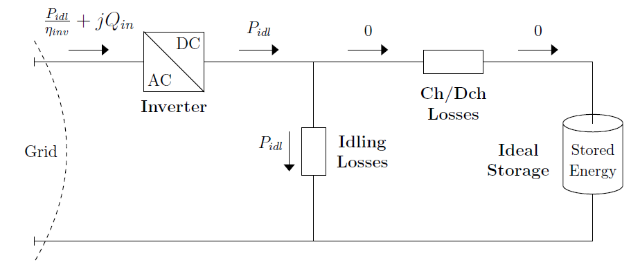
Figure 4. The Internal Power Flow of the Storage Element during Idling State
1, 2 Note that the powers at the interface with the grid may differ from the specified ones due to the inverter capability curve and the model selected for variation with voltage (see property model).
3 In practice, this is how storage systems operate. Typically, the storage systems maintain a certain SOC, which means that some charging is done to account for the self-depletion and auxiliary loads supplied by the same inverter.