Support (Discharging) and Time (Charging)
To demonstrate the StorageController operation in Support mode, a generator has been added to the circuit as shown in Figure 15.
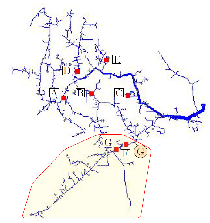
Figure 15: IEEE 8500 buses test case with location of storage fleet and the generator added
Only the two storage elements located downstream of the generator will participate in the regulation, i.e., storage F and G.
Thus, these two elements are explicitly specified in controller’s ElementList property. Their ratings have also been intentionally increased so they can provide full support to the generator. The power monitored by the controller has been set to the first line segment upstream the generator such that both the generator and the storage fleet will directly affect it. The controller target has been set to 2000kW. This means that whenever the power exported from the zone highlighted in Figure 15 is less than the target, the controller will dispatch the fleet to provide the necessary support.
New LoadShape.DGdispatch npts=24 interval=1 mult=[0.78,0.65,0.65,0.67,0.70, 1,0.98,0.97,0.9,0.83,0.8,0.79,0.85,0.84,1,0.4,0.35,0.32,0.3,0.32,0.35,0.4,0.8,1]
New Generator.G model=1 bus1=m1108295 kW=8000 daily=DGdispatch kV=12.47
~ vmaxpu=1.2 vminpu=0.8
New Monitor.Pmon element=Line.LN6351524-1 terminal=2 mode=1 ppolar=no
New StorageController.SC element=Line.ln6351524-1 terminal=1 modedis=support
~ kwtarget=2000 modecharge=Time timeChargeTrigger=2 %rateCharge=50 MonPhase=AVG
~ elementList=[FG] %reserve=20 eventlog=yes
Edit Storage.FkWrated=1500 kVA=1500 kWhrated=8500 %stored=70
Edit Storage.GkWrated=500 kWrated=500 kWhrated=3500 %stored=70
A simplified single-line diagram is shown in Figure 16 with all relevant elements and measures. PSC corresponds to the power monitored by the controller. It is negative if the lower portion of the circuit exports power to the upstream section, satisfying the sign convention adopted for this mode.
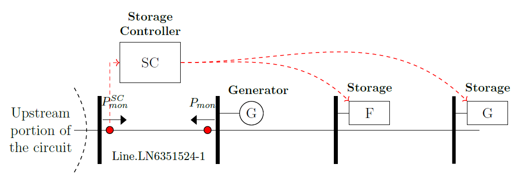
Figure 16: Simplified single-line diagram of lower portion of the circuit
Figure 17 shows that the fleet composed by storage F and G can provide support to the generator when the exported power drops below 2MW, which happens between 4pm and 10pm. Note that the charging of the fleet has the same effect of additional loads in the lower portion of the circuit, reducing the amount of power exported.
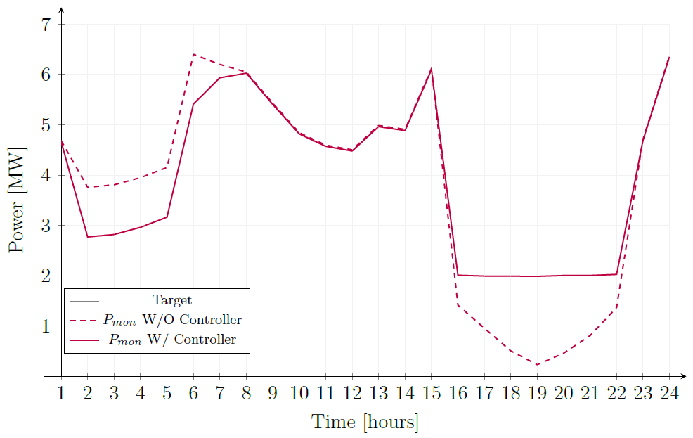
Figure 17: Powers entering the second terminal of the monitored line element