Three-Winding Transformers
Three-Winding Transformers
A three-phase model of a three-winding transformer used in the calculation of GIC is shown in Figure 45. Note that the delta tertiary winding is not included in the model since it does not have any physical connection to ground. Thus, the same model can be used for both two winding and three winding transformers. The neutral nodes of both of the wye windings (i.e. X0 and H0) are modeled explicitly. In some cases, either the X0 or H0 bushing may be ungrounded. In the GIC model, the node can be grounded through a large resistance, e.g. 1 MΩ to represent such connections.
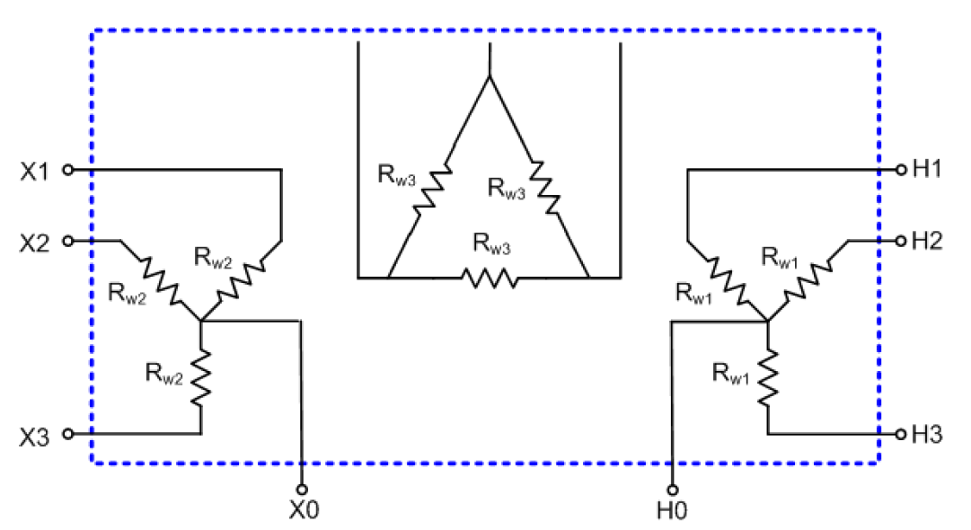
Figure 45. Three-phase Model of a Three-Winding Transformer (Grounded-Wye,
Grounded-Wye, Delta)
Rw1 and Rw2 are defined as the dc winding resistance values of the high voltage or extra-high voltage and medium voltage windings, respectively. Rw3 is defined as the dc winding resistance values of the low voltage tertiary winding; however, it is not included in the DSS model since it has no physical connection to ground.
Transformer windings are modeled in DSS with resistive branch circuits as shown in Figure 46.
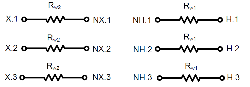
Figure 46. Two-winding and Three-winding Transformer model in DSS
The winding terminals designated as NH.1, NH.2, NH.3 and NX.1, NX.2, NX.3 in Figure 46 must be connected together to construct each of the wye windings. The bus numbers are arbitrary, but typically the name of the high side bus is used with the next available terminal number. An example OpenDSS script with high voltage bus named ‘Bus1’, low voltage bus named ‘Bus2’, dc winding resistance of 0.2 Ω/phase for the H winding and 0.1 Ω/phase for the X winding is as follows:
New GICTransformer.T1 busH=Bus1.1.2.3 busNH=Bus1.4.4.4 busX=Bus2.1.2.3 busNX=Bus1.5.5.5 R1=0.2 R2=0.1 type=YY