Generalized Transformer model
Generalized Transformer model
The DSS Transformer model has several interesting features that may not be obvious from inspecting the computer code. Thus, this document is prepared to describe the theory behind the model and how the generalized model is put together inside the DSS.
Introduction
The DSS builds a general N-phase, M-winding transformer model with two terminals for each winding as indicated in the figure below.
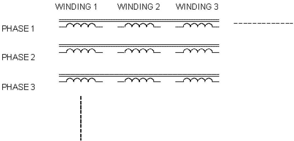
The terminals are connected according to the user’s specifications to form whatever connection is desired. The process eventually yields a primitive Y matrix that is included in the overall system admitance matrix. For example, to represent a Delta/Wye/Wye three-phase transformer, a three-winding
transformer is defined as is connected as shown in the figure below.

Note that all terminals of each class of DSS devices must have the same number of total conductors (phase and neutrals). The three-phase transformer has 4 conductors per terminal. The 4th conductor on the delta winding is not connected to anything inside the transformer model.
Handling the Inversibility Problem
The nodal admittance matrix of the model in the previous figure may not be inversible, depending on the rest of the system model. Because the delta winding has no inherent reference to ground, the primitive Y matrix will not be inversible. Whether the system Y matrix is inversible depends on what gets connected to the delta side. This is a common problem to all admittancebased simulation programs. If the user neglects to connect anything to the delta side, the solution will fail. We decided that the DSS ought to be a little more user friendly. Therefore, the DSS model, by default, adds a reactance of 1 ppm of the transformer's rating to each terminal. This has the effect of hanging a high impedance to ground off the terminal as shown in the figure below.
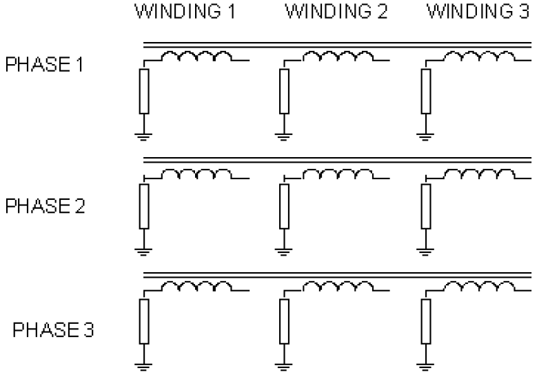
You can change this value by setting the PPM_AntiFloat property of the transformer. If the network on all windings has a solid ground reference, you may set this property to zero.
Therefore, an inversible matrix is achieved for all winding connections. Since all math in the DSS is performed double precision (64bit), 1 ppm is handled without much difficulty. It does introduce a slight error, but that is minimal and usually not of consequence. This allows the user to worry less about transformer connections and isolated circuits. This does not imply that there will not be convergence problems even if a solution can be achieved for the system Y matrix. Since the impedance to ground looking into the delta winding is high, current injections may cause very high estimates of voltage during the iterations and throw off the convergence.
Building the Transformer Y Primitive Matrix
The method described here is very similar to the one Roger Dugan developed to model internal transformer transients, where one may be dealing with 70 or more windings. The basic input data are the PERCENT short circuit impedances between each pair of windings. This data should be readily available. There are M(M-1)/2 such impedance values.
A multi-ported network referenced to ground that will give the same impedance results is created on a 1.0volt base. There is one terminal per port; the second is implicitly grounded. The multi-ported network thus constructed is referenced to the actual windings by ideal transformers of the appropriate turns ratio. The figure below illustrates the process and model.
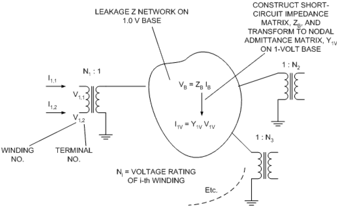
The process is as follows:
•First, the short circuit impedance matrix, ZB, is constructed on a onevolt base. Any base could be chosen, but this is convenient because the turns ratio of the windings corresponds to the voltage rating of the winding. ZB uses winding 1 as the reference winding.
•It is then transformed to nodal admittance form, yielding the nodal admittance matrix for the onevolt multiport equivalent network.
•The ultimate goal is to obtain the admittance matrix for the transformer in actual values. This is accomplished by applying the turns ratios of the ideal transformers to create the nodal admittance formulation for the actual winding terminals, YT, in which both terminals of each winding are explicitly modeled.
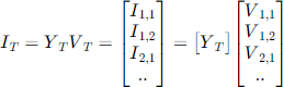
This matrix can be used as a primitive Y matrix to develop a computer model for any connection of the windingterminals simply by adding into a system Y matrix in the usual fashion for building system models.
Constructing ZB
Using winding 1 as the reference, we construct the equation:
1. Compute ZBASE for 1-volt base, convert percent short circuit Z’s to per unit.
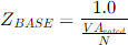
where,
N = No. Phases;
VA = total transformer VA rating
2. Diagonal Elements:

where
ZSCij = per unit short circuit impedance between windings i and j.
3. Off diagonal Elements:

i<> j > 1
ZB is of order M1;
only rows and cols [2..M] are used).
Transforming ZB to Y1V
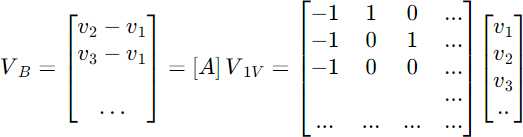
This transformation is a simple power invariant reference frame change that changes the voltage reference from the winding 1 voltage to the remote ground voltage (as in all nodal Y formulations).
We have,
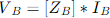
We want

Order of VB is (M-1). Order of V1V is M.
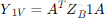
The currents transform as

Apply this transformation to ZB


Pre-multiply both sides by AT:

Therefore,
Transforming Y1V to YT
Now that we have the nodal admittance matrix of the leakage impedance network on a 1-volt base, we can perform a similar transformation to convert to the actual winding terminals reference frame. We have

We want

Voltage transformation:

Where Ni = Turns ratio (actually, voltage rating) of ith winding
Current transformation:

Applying the transformation, we will arrive at:
This matrix is in actual ohmic values and can be used to construct any transformer connection feasible.
Algorithm for Constructing YPRIM for a Given Connection
The primitive Y matrix, YPRIM, that can be used to represent a particular connection of an N-phase transformer in the system Y matrix is constructed using the triple-nested For loop shown below. It is assumed that each phase has identical leakage impedances.
1. Clear YPRIM=[0]
2. For i = 1 to 2M
a. For j = 1 to i
i. For k=0 to N1 (phase loop)
YPRIMmn = YPRIMmn + YTij
where,
m = TermRef(i + 2Mk)
n = TermRef(j + 2Mk)
ii. Set YPRIMnm = YPRIMmn (for symmetry)
Note that YT is built for only one phase and is then added into YPRIM N times. The TermRef array is an array of indices that relates the terminals of the winding to the DSS terminal and conductor in the final model. For example, consider the DeltaWye connection shown in the diagram below: Since the DSS requires that all electrical terminals of a device have the same number of conductors, there will be two 4-conductor terminals. The order of the YPRIM matrix is (N+1)M = (3 +1)2 = 8. Thus, YPRIM for a three-phase, two-winding transformer will be an 8x8 matrix. The first 4 elements of the matrix correspond to the first DSS terminal, the next 4 the second terminal, and so on, if there are more windings in the transformer model.

There are two possible ways to connect the Delta winding. The phase rotation is automatically selected in the DSS so that the secondary (low voltage) winding lags the primary (high voltage) by 30 degrees in Y/Delta connections. (Currently, if you want a different angle shift, you must construct a transformer bank of 3 single-phase transformers.) The 4th conductor of the delta winding is not connected to anything inside the model. All the elements of the corresponding row and column of the YPRIM matrix will be zero. By default, the 4th terminal is connected to Node 0 of the bus to which the terminal is connected. Thus, it is inconsequential for the delta-winding case, but could have side effects for the Wye-connected winding.
The TermRef array for this connection is as follows:
Array Index, Winding, Winding Terminal, TermRef(Index)
1 1 1 1 (Phase 1)
2 1 2 3
3 2 1 5
4 2 2 8 (neutral)
5 1 1 2 (Phase 2)
6 1 2 1
7 2 1 6
8 2 2 8
9 1 1 3 (Phase 3)
10 1 2 2
11 2 1 7
12 2 2 8
Thus, the process of generating the YPRIM matrix is to first generate the TermRef array showing the coincidence the DSS conductor number with the winding terminal of the transformer model and then to plug it into the deceptively simple algorithm described above. It looks like magic, but it works! Theoretically, any connection could be represented this way.
Currently, the DSS generates TermRef arrays for only Delta or Wye connections according to the following rules:
Phases=1 Connection=Delta: Line-to-line connected winding. Define base voltage as line-to-line kV There are always N+1 conductors per terminal on a transformer. Therefore, there are two conductors per terminal. Explicitly connect the second conductor where it belongs. Otherwise, it will be connected to Node 0, which is probably NOT what you want. YT is essentially copied to YPRIM.
TermRef is [1, 2, 3, 4, …].
Phases=1 Connection=Wye: LinetoNeutral connected winding. Define base voltage as line-to-neutral kV. Second conductor is automatically connected to Node 0 of the bus. YT is essentially copied to YPRIM.
TermRef is [1, 2, 3, 4, …]
Phases=2 Connection=Wye: Assumes 2 phases of a 3phase bank, which is common in North America. Therefore, the winding voltages are the specified voltage rating divided by  . Specify kV lineline as the rated voltage. Three conductors; 3rd defaults to ground. If the Wye winding is the first winding,
TermRef is [1 3 … 2 3 …], where … represents connections of other windings.
Phases=2 Connection=Delta: Treated like an opendelta bank. Only three conductors per terminal. Explicitly connect the terminals because the phase connection is ambiguous here. Specify voltage as linetoline kV. If the Delta winding is the first winding,
TermRef is [1 2 … 2 3 …] or [1 3 … 3 2 …] where … represents connections of other windings.
Phases=3 Connection= Wye or Delta: Standard 3phase connections. LV lags HV in mixed connections. 4 conductors per terminal. Specify voltage rating in linetoline kV. (See example above for TermRef.)
Phases>3 Connection= Wye: Specify voltage rating of winding (phaseneutral) in kV. Windings are connected in star with the second winding terminal always connected to the star point.
Phases>3 Connection= Delta: Specify voltage rating of winding (phasephase) in kV. Windings are hooked in series with the last phase being connected back to the first. The direction is determined by same rule as for 3phase transformers (LV lags the HV).
Handling Neutral Impedances in Wye Windings
See also TechNote OpenDSS Neutral Rules. This has been revised.
Note that there is a series R-X impedance in the neutral of wye-connected windings in the DSS. This is to avoid having to enter a separate impedance branch for the neutral, if a neutral impedance exists. It is strictly for user convenience. However, it can generate some confusion.
The default is for RN=-1, signifying that the implicit neutral of the transformer winding is OPEN. If RN = XN= -1, the neutral would be grounded. Because admittances are needed in the YPRIM matrix, a large conductance of YN = 106 + j0 is added to the appropriate diagonal element of
YPRIM. This corresponds to 1 microohm.
To specify an open (floating) neutral, specify RN less than zero (a physical impossibility). This is a flag to the DSS to enter the neutral admittance as YN = 0+jN . (i.e., no conductance)
Using Neutral Impedance with DSS Connection Defaults
Defining the neutral impedance is only part of the issue. Since the transformer is declared to be a 3phase device in this case, the 4th terminal is automatically connected to Node 0 of the bus. This is ground. (The default connection spec for a 3phase
device is “busname.1.2.3.0.0.0. …”)
Thus, any neutral impedance would be shorted by default. To allow the neutral impedance to enter the circuit, connect the 4th conductor of the terminal to an unused node on the bus, for example:
New Transformer.T1 … wdg=2 bus=Secbus.1.2.3.4 …
See TechNote OpenDSS Neutral Rules for additional rules.
To avoid confusion with this, many DSS users use the Reactor object to add the neutral impedance separately.