The Universal Power Flow Controller (UPFC) model developed for EPRI’s OpenDSS corresponds to an equivalent representation for applications on Distribution Systems (DS), where the aim is to regulate voltage for a part of the system and to compensate reactive power to fix a desired power factor (PF). In the current version, the UPFC control actions have been moved into the control queue in OpenDSS, this to make it more stable and improve the accuracy of the model when widely deployed across a medium/large-scale circuit model.


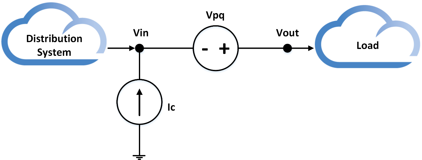
Figure 1. General architecture of the UPFC device


This model is a steady state model and can be used for simulations in sequential-time mode.  The variables defined to configure this device allows to configure the set point in terms of the output voltage and PF. Additionally, this generalized model allows to specify the maximum rating for the compensating voltage source (Vpq) and the losses behavior as a function of the input voltage by using XY curves. These variables are described as follows:


Bus1                

Name of bus to which the UPFC's first terminal (input terminal “Vin”) is connected. Remember to specify the node order if the terminals are connected in some unusual manner.

Bus2              

Name of bus to which the UPFC's second terminal (output terminal “Vout”) is connected. Remember to specify the node order if the terminals are connected in some unusual manner.

RefkV           

The set point in kV for the voltage regulation controller. The default value is 0.24

PF                   

The desired power factor to be compensated by the UPFC. The default value is 1.

Frequency   

Frequency of the system. Defaults to circuit fundamental frequency.

Phases          

Number of phases of the device, the default value is 1.

Xs                  

Impedance in ohms of the series transformer of the UPFC (2πfL). By default, is 0.745 Ω (2mH – 60Hz)

Tol1              

Corresponds to the desired tolerance for the control algorithms of the UPFC, the default value is 0.02 (2%)

Mode            

Number (integer) specifying the operation mode. The UPFC has 4 modes of operation:

0: The controllers are turned off; this means that the UPFC will behave as a series impedance with value Xs for all the phases.

1: Voltage regulation mode. In this mode the UPFC only regulates the output voltage; however, there is no reactive compensation. The set point is the one specified in the property RefkV.

2: Reactive power compensation. In this mode the UPFC will compensate reactive power and try to fix the PF programmed in the property PF. There will be no voltage regulation.

3: Dual control mode. In this mode the UPFC performs voltage regulation and reactive power compensation. Both controllers will follow the set points programmed in the properties RefkV and PF.

4: It is a control mode where the user can set two different set points to create a secure GAP, these references must be defined in the parameters RefkV and RefkV2. The only restriction when setting these values is that RefkV must be higher than RefkV2

5: In this mode the user can define the same GAP using two set points as in control mode 4. The only difference between mode 5 and mode 4 is that in mode 5, the UPFC controller performs dual control actions just as in control mode 3.


VpqMax        

It is the maximum voltage (in Volts) that the series voltage source (Vpq) can provide. By default, is 24 V.

LossCurve   

It is the name of the XY curve that describes the losses as a function of the input voltage.

BaseFreq    

Base Frequency for impedance specifications. Default is 60 Hz.

enabled    

{Yes|No or True|False} Indicates whether this element is enabled

Like             

Name of an existing UPFC object on which to base this one.

VHLimit     

High limit for the voltage at the input of the UPFC, if the voltage is above this value the UPFC turns off. This value is specified in Volts (default 300 V)

VLLimit      

Low limit for the voltage at the input of the UPFC, if voltage is below this value the UPFC turns off. This value is specified in Volts (default 125 V)’;

CLImit        

Current Limit for the UPFC, if the current passing through the UPFC is higher than this value the UPFC turns off. This value is specified in Amps (Default 265 A)

RefkV2          

The set point in kV for the voltage regulation controller for control modes 4 and 5. The default value is 0

kvarLimit    

This value is the maximum amount of reactive power (kvar) that the UPFC can compensate. (Default 5kvar)

Element      

The name of the PD element monitored when operating with reactive power compensation. Normally, it should be the PD element immediately upstream the UPFC. The element must be defined including the class, e.g. Line.myline.


After defining the UPFC device(s) in the model, it is necessary to define an UPFC controller to coordinate the control actions. If the UPFC controller is not defined, the UPFC device(s) will not perform any control action. The UPFC Controller has just a few properties, the only one to consider is UPFCList, in which the user can define the UPFCs that will operate. If this property (UPFCList) is not defined, all the UPFCs in the model will operate. Define the UPFCControl after defining the UPFCs as follows:


New UPFCControl.myUPFCCtrl


Or in case the list of UPFCs will be defined:


New UPFCControl.myUPFCCtrl UPFCList=[myupfc1, myupfc2, …]


For more information, check the example located here:

 https://sourceforge.net/p/electricdss/code/HEAD/tree/trunk/Version8/Distrib/Examples/UPFC_Test/