Dynamics
Consider the following declaration in OpenDSS for a WindGen object.
...
New XYcurve.generic npts=4 yarray=[0.44 0 0 -0.44] xarray=[0.95 0.98 1.02 1.05]
New XYcurve.PLosses npts=19 yarray=[43.7934 25.71 16.5371 11.45 8.422 6.5199 5.2913 4.4653 3.37 2.34 1.31 0.289 0.28 0.28 0.28 0.28 0.28 0.28 0.28] xarray=[5 6 7 8 9 10 11 12 13 14 15 16 17 18 19 20 21 22 23]
New WindGen.wtg1 phases=3 bus1=WTG1INT kV=0.69 kVA=3600.0
~ model=1 Xthev=0.05 Vss=1.0 Pss=0.8 Qss=0.0 vwind=10
~ N_WTG=1 SimMechFlg=1 APCFLG=1 delt0=0.0001 DebugTrace=0 VV_Curve=generic
new monitor.WindGen element=WindGen.wtg1 terminal=1 mode=3
new monitor.WindGenXfmr element=transformer.wtggsu terminal=1 mode=0
new monitor.WindGenXfmrPQ element=transformer.wtggsu terminal=1 mode=1
~ ppolar=no
set voltagebases = [12.47, 0.69]
Calcv
set maxiterations=100
solve
set mode=dynamics h=0.001 ControlMode=OFF stepsize=0.001
set StateVar = WindGen.wtg1 QMode 2
Solve number=2590
WindGen.wtg1.vwind=12
Solve number=4590
Solve number=10590
...
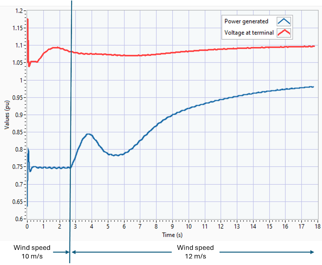
The extract above corresponds to the declaration and dynamic simulation of a proposed WindGen object in OpenDSS. This simulation with a 1 ms step resolution demonstrates the WindGen electromechanical transients when after 2.5 seconds the wind speed abruptly increases by 2 m/s. The results of this simulation are shown in Figure 9. Error! Reference source not found.Figure 9 also displays the voltage behavior for the same simulation but extended up to 17 seconds. Both curves show the voltage control performed by the device according to the configuration proposed above.
The voltage response to wind speed variation can also be appreciated in Figure 9, following the set point within the control algorithm depending on the user settings. The outputs and state variables have been integrated into OpenDSS and can be queried using standard OpenDSS recording objects such as monitors.

Figure 11. Active power output for the simulation, wind change at 1.5 seconds
Example 2
Consider the WindGen declaration presented in the previous example, but instead of just starting the WindGen and change the speed a single-phase fault occurs 7.1 seconds after starting the simulation at bus 68211- phase 3 (10 mi upstream from the WindGen location). The fault is cleared after 700 ms and then the simulation goes for another 10.5 seconds. The code for implementing this sequence of events is as follows:
...
set mode=dynamics h=0.001 ControlMode=OFF stepsize=0.001
set StateVar = WindGen.wtg1 QMode 2
Solve number=2590
WindGen.wtg1.vwind=12
Solve number=4590
New Fault.myFault phases=1 bus1=68211.3
Solve number=700
Fault.myFault.enabled=False
Solve number=10590
...

Figure 12. WindGen response when exposed to a single-phase fault
AS can be appreciated in Figure 10, the WindGen response describes a behavior like the one obtained the previous example for the first 7.1 seconds. Then, after the fault is introduced, the transient occurring given the fault type and duration. Once the fault is cleared the WindGen keeps following its control consign, stabilizing the power output oscillations in time to reach out the set point posed by the controller.
