Steady state
Consider the following declaration in OpenDSS for a WindGen object.
...
New line.line1 phases=3 bus1=77071 bus2=WTG1EXT switch=true
New transformer.wtggsu phases=3 windings=2 xhl=6.826
~ wdg=1 bus=WTG1INT conn=wye kv=0.69 kva=3600.0 %r=0.438
~ wdg=2 bus=WTG1EXT conn=delta kv=12.47 kva=3600.0 %r=0.438
New XYcurve.generic npts=4 yarray=[0.44 0 0 -0.44]
~ xarray=[0.95 0.98 1.02 1.05]
New XYcurve.PLosses npts=19 yarray=[43.7934 25.71 16.5371 11.45 8.422 6.5199 5.2913 4.4653 3.37 2.34 1.31 0.289 0.28 0.28 0.28 0.28 0.28 0.28 0.28] xarray=[5 6 7 8 9 10 11 12 13 14 15 16 17 18 19 20 21 22 23]
New WindGen.wtg1 phases=3 bus1=WTG1INT kV=0.69 kVA=3600.0
~ model=1 vwind=12 ag= 1 90 / Lamda=7.95
~ VV_Curve=generic
~ PLosses=PLosses
...
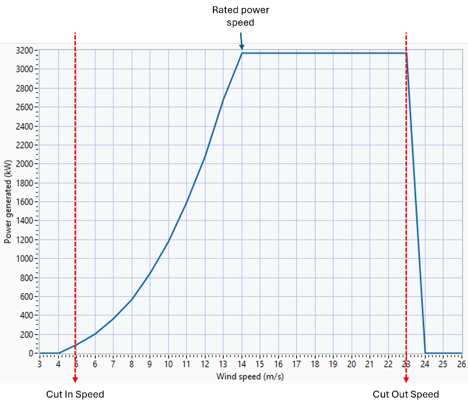
This model corresponds to a 3.6 MVA wind generator ready to operate for steady state or QSTS simulations. This configuration preserves most of the default values for the sake of the example. With this configuration the power generation under variable wind speed will be as shown in Figure 5. The output depicted in Figure 5 matches with the expected behavior, which includes the mechanical and electric features of the model proposed.

Figure 9. Power output for the WindGen object declared under increasing wind speed

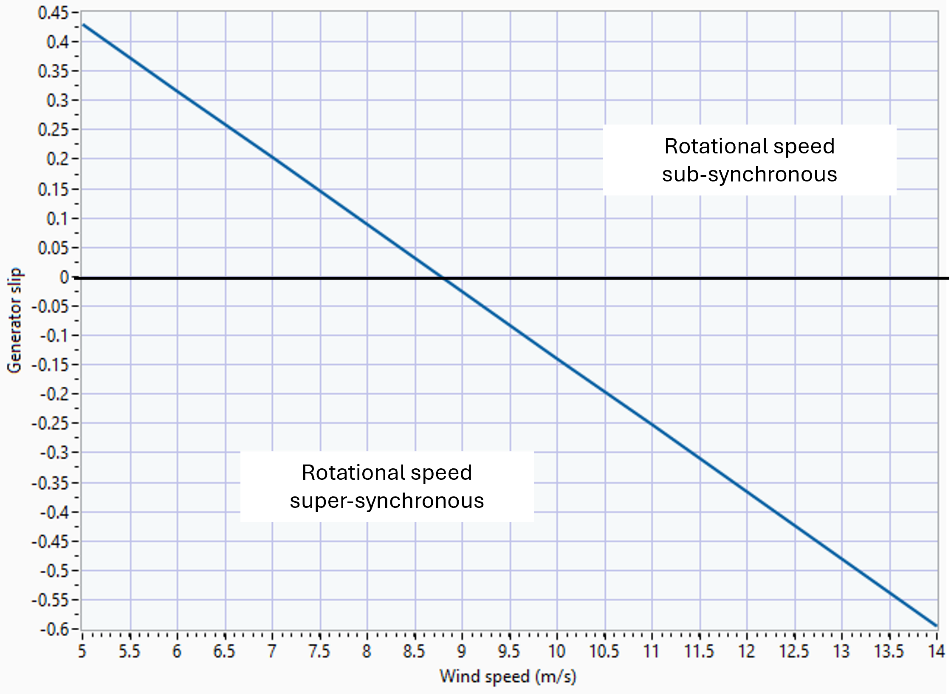
Figure 10. Generator’s slip under increasing wind speed
This model also allows to generate/absorb vars based on the PF property and the VV_Curve (if declared) for providing volt-var control. The DC/AC ratio will be defined by the PF property. The calculation of the generator slip allows to calculate and report the stator and rotor powers within the Wind generator.
