Examples
In this section, a few examples are presented to show different aspects of the inverter modelling described throughout this document. For simplicity and easy reproducibility, a small circuit containing a single storage connected to a voltage source will be utilized, as shown in Figure 5.
The base script utilized in all examples is provided below. This script and also all the other scripts used to generate the examples are available in OpenDSS “Examples\InverterModels\InverterTech− Note ” folder.
!Base Circuit with a Single Storage
Clear
New Circuit.Source bus1=A basekv=13.8 phases=3 pu=1 Z0=[10,10] Z1=[10,10]
!Inverter Efficiency Curve
New XYCurve.Eff npts=4 xarray=[.1 .2 .4 1.0] yarray=[.86 .9 .93 .97]
New Storage.A phases=3 bus1=A kv=13.8
~ %charge=100% discharge=100 %reserve=20
~ %effcharge=90 %effdischarge=90
~ %idlingkW=2
~ kWhrated=10000 %stored=80 state=idling
~ dispmode=default model=1 kVA=1000 kWrated=900 kvarMax=800 %kWRated=100
~ EffCurve=Eff %cutin=5 %cutout=5 varfollowinverter=false wattpriority=True
~ %PminkvarMax=20 %PminNoVars=10
~ vminpu=0.8 vmaxpu=1.2
New Monitor.MonStorageAState element=Storage.A mode=3
New Monitor.MonStorageAV element=Storage.A mode=0
Set voltagebases=[13.8]
Calcvoltagebases
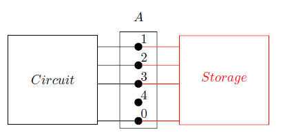
Figure 5: Storage Element Connected directly to a Voltage Source