Operation with different Priorities: kV A Violation Only
This example illustrates the violation of the inverter kVA rating considering active power, reactive power and power factor priorities. Besides the base script, the following script has been utilized.
! kVA Violation Only
New LoadShape.dispatchFollow interval=1 npts=24 mult = [ 0.0, 0.01 , 0.08,
0.12 , 0.16 , 0.30 , 0.50 , 0.96 , 0.0 , 0.0 , 0.0 , 0.0 , 0.0 , 0.0 , 0.0 , 0.01 ,
0.08 , 0.12, 0.16, 0.30, 0.50 , 0.96 , 0.0, 0.0 ]
Edit Storage.A dispmode=follow daily=dispatchFollow pf=0.8
! P Pr i o r i t y
Set casename=Ppriority
Edit Storage.A wattpriority=t rue
! QPriority
! Set casename=Qpriority
! Edit Storage .A wa t t p r i o r i t y=f a l s e
! PF Pr i o r i t y
! Set casename=PFpr ior i ty
! Edi t Storage .A PFpr ior i ty=t rue
Set mode=Daily
Set maxcontroliter=50
Set stepsize=1h
Solve
Export monitors Mon StorageA
First, a loadshape is specified to drive the storage active power dispatch in “Follow” mode. Then, the storage element definition is edited to enable the operation in the desired mode. Constant PF reactive power dispatch mode is also enabled, with a power factor of -0.8.
Next, wattpriority and PFpriority are set. Note that only one case can be run at each time. Finally, the solution settings are specified. The simulation is solved in daily mode and the monitors are exported.
Figure 6 shows the PQ plane with all operating points for each of the priorities. They correspond to the state variables kWOut and kWIn exported from monitor Mon StorageA State. Note that all operating points lie on the constant power factor line for all three priorities, except during the following time instants:
- The two-time instants (one while in charging state and the other while in discharging state) in which the inverter kVA has been violated and for both active and reactive power priorities. These two operating points correspond to the multiplier -0.96 and 0.96 for charging and dis- charging, respectively. For further details about storage operation in “Follow” dispatch mode, see [3];
- For the time instants when the active power lies within the region between %CutIn/%CutOut and %PminNoVars (W Only), in which only active power dispatch is allowed;
Also note that as varFollowInverter has been set to “false”, the operating points for the time instants when the storage is in idling state also lie in the constant power factor line, even though the inverter status is OFF. The small active power that charges the element during this state is due to idling losses (see [3]).
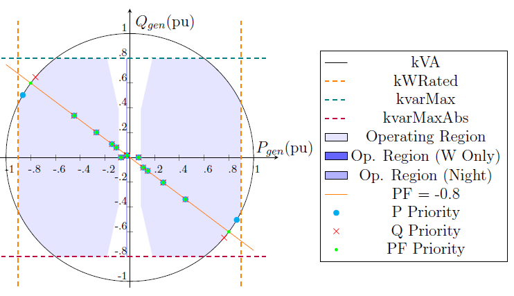
Figure 6: PQ Plane with Inverter Capability Curve and Operating Points under Constant PF Mode