Modeling
Figure 1 shows the voltage source modeling in OpenDSS. Note that it is a two-terminal element (like lines and transformers), where the second terminal is connected to node 0, which is always grounded, of the same bus of the first terminal for all phases.
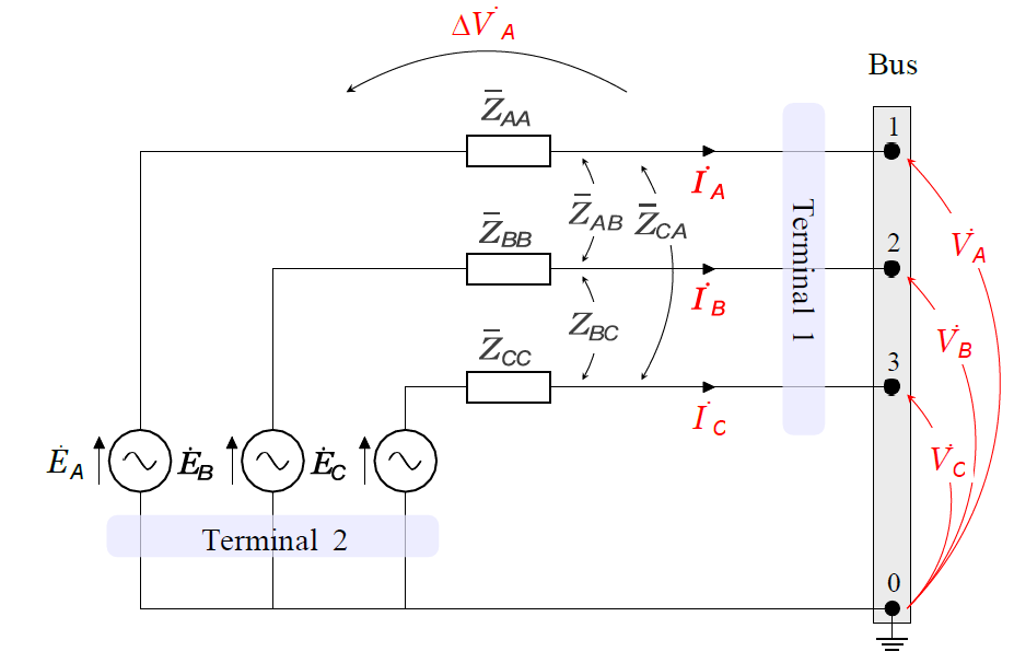
Figure 1: Electrical Model of the Voltage Source Element
By default, this element corresponds to a 3-phase symmetric voltage source, i.e., three sinusoidal single-phase voltage sources with the same magnitude and phase angles shifted by 120°. Furthermore, the self series impedance at each phase and the mutual series impedance between phases are equal, as shown in expressions (1) and (2), where Z¯s and Z¯m are defined as self and mutual impedance, respectively.


Note: OpenDSS doesn’t support a perfectly ideal voltage source, but, for all practical effects, this can be accomplished by setting (1) the source impedances to a very low value or (2) or by setting its “model” property to “ideal”, which essentially assigns a tiny impedance to the source.
Z¯s and Z¯m impedances are not commonly utilized to specify voltage source impedances in power flow tools. One of three different ways are utilized instead: sequence impedances, short-circuit powers or short-circuit currents. In the next sections, it is demonstrated how to obtain those parameters and the relation between them.