Power delivered to the circuit
The steps taken to obtain the power delivered to the circuit in the time step, t, are presented in this section. This process can be repeated multiple times for the same time step, t, within the control loop if there is an InvControl element controlling this PVSystem.
Step 1: Calculation of PV array’s output power The irradiance at a time step, t, is converted into PV array’s DC output power, Pdc[t], according to Equation 1.

Where:
- irradiance: Base value of irradiance in kW/m2. For static simulations, this value represents the present irradiance on PV array and therefore there is no need to define irradiance[t];
- irradiance[t]: Value of the yearly, daily or duty irradiance curve in the time step, t;
- PTCurve(Temperature[t]): Value of the correction factor in the time step t due to the tem- perature Temperature[t];
- Temperature[t]: Value of the temperature curve in time step t. For static simulations, however, the user must set the present temperature Temperature instead of this property.
Besides the inverter efficiency curve, another simplification of the model considers that the ratio of PV array’s output power, Pdc, to irradiance is linear, as can be seen in the Simplified curve (red curve) of Figure 6, however, the relationship between them, Real curve, is not constant for the entire range of irradiance values. It should be noted that the Real curve (blue curve) of Figure 6 does not correspond to a measured curve, it is just illustrative.
Step 2: Checking the PV inverter status The inverter status at time step t depends on its status in the previous time step, t − 1, as shown below.
When the inverter status is OFF in t - 1, it means that Pac[t - 1] = 0. It is turned ON in t according to Equation 2.

When the inverter status is ON in t - 1, it means that Pac[t - 1] > 0. It is turned OFF in t according to Equation 3.

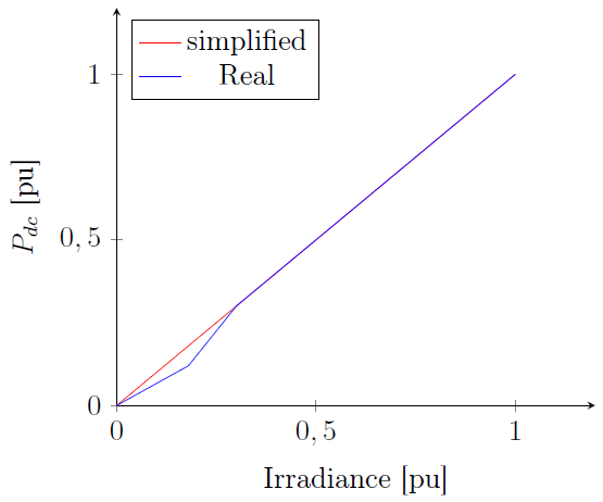
Figure 6: PV array output power vs Irradiance
One model constraint is the need to have %cutout less than or equal to %cutin.
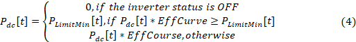
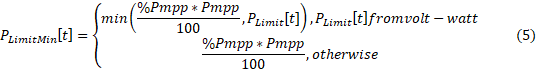
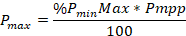
Step 3: Calculation of the inverter desired active output power The inverter desired active output power is calculated by Equation 4. In this step, the maximum active power limit is also verified by means of the %Pmpp property of the PVSystem and the active power limit, PLimit[t], resulting from an eventual operation of the volt-watt function of an InvControl element that might be controlling the PVSystem.
Where:
Step 4: Specification of inverter desired reactive power The inverter desired reactive power, Qtac, is defined separately from the active power and can be specified as either a fixed kvar value,
using the kvar property, or as a function of a constant power factor using PF property. In the first case, the inverter must try to keep the value of the reactive power constant and equal to kvar, regardless of the present value of the output active power. In the second case, which corresponds to the smart inverter function named as constant power factor, the inverter changes the reactive power to maintain the nominal power factor. Another way of setting the desired value of the reactive power, Qtac, is done by the operation of a few functions of the InvControl element, as shown in the section 2.
Step 5: Checking the inverter reactive power limits The desired reactive power after the verification of its limits is presented in equations 6 and 7. Equation 6 is used when the desired reactive power, Qt [t], is positive and, Equation 7, when it is negative.


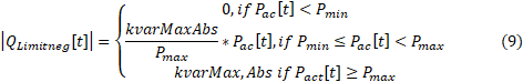
Equation 8 and Equation 9 present the limits of the provided and absorbed reactive power, respectively, as a function of the active power delivered to the grid.

Where:

If the inverter status is OFF, Qttac[t] can only be non-zero when the VarFollowInverter property is set to NO or False.
Step 6: Checking inverter capability The maximum inverter capacity corresponds to its kVA rating. Active and reactive power that are delivered to the grid can be defined according to Equations 10 and 11 when the inverter capacity is not exceeded.


If its capacity is exceeded, the PV inverter limits the value of its kVA rating, kV A property. As a result, P’ac[t] and/or Q”ac[t] should be reduced to meet one of the following 3 priorities:
- Power factor priority Equations 12 and 13 present the values of the active and reactive power that are delivered to the grid when the inverter capacity is exceeded under power factor priority.


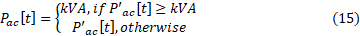
- Active power priority Equation 14 presents the new reduced value of the reactive power that is delivered to the circuit when the inverter capacity is exceeded under active power priority. If the active power is greater than or equal to the capacity of the inverter, the new value of the active power that is delivered to the grid becomes the kVA rating and therefore, there is no room for reactive power, according to Equation 15.

- Reactive power priority Equation 16 presents the new reduced value of the active power that is delivered to the circuit when the inverter capacity is exceeded under reactive power priority. If the reactive power is greater than or equal to the capacity of the inverter, the new value of the reactive power becomes the capacity of the inverter itself, according to Equation 17, but this can only happen if the inverter is capable of providing or absorbing reactive power without any active power, in other words, when the VarFollowInverter property is set to either NO or False.


Finally, the apparent power provided by the PVSystem in a time step t can be written according to Equation 18.
