PV inverter properties
The inverter properties that may be defined in the model are:
- kVA: Inverter’s kVA rating;
- kV : Nominal rated (1.0 per unit) voltage, kV, for PVSystem element:
- If 3-phase PVSystem elements, specify line-to-line kV;
- If 1-phase wye (star or LN), specify line-to-ground kV;
- If 1-phase delta or phase-phase connected, specify line-to-line kV.
- Phases: Number of Phases of PVSystem element;
- bus1 : Bus to which the PVSystem element is connected. May include nodes definition;
- conn: Connection of PVSystem element;
- PF : Power factor for the output power (AC power). Setting this property will force the in- verter to operate in CONSTANT POWER FACTOR MODE. By definition, when this value is negative, the inverter absorbs reactive power (inductive characteristic) and, when positive, it provides reactive power (capacitive characteristic);
- kvar : Output reactive power. Setting this property forces the inverter to operate in CON- STANT kvar MODE. When this value is negative, the inverter absorbs reactive power (induc- tive characteristic) and, when positive, provides reactive power (capacitive characteristic);
- %Pmpp: Upper limit on output active power as a percentage of Pmpp;
- %cutin: Percentage of inverter’s kVA rating, see kVA property. When the inverter is OFF, the power from the PV array (DC power) must be greater than this value for the inverter to turn ON;
- %cutout : Percentage of inverter’s kVA rating, see kVA property. When the inverter is ON, it turns OFF when the power from the array (DC power) drops below this value;
- kvarMax : Maximum value of reactive power, in kvar, that the inverter can provide to the grid;
- kvarMaxAbs: Maximum value of reactive power, in kvar, that the inverter can absorb from the grid (as an un-signed value);
- VarFollowInverter : Boolean variable which indicates that the reactive power does not respect the inverter status.
- When set to True, PVSystem’s reactive power will cease when the inverter status is OFF, due to the power from PV array dropping below %cutout. The reactive power will begin again when the power from PV array is above %cutin;
- When set to False, PVSystem will provide/absorb reactive power regardless of the status of the inverter.
- WattPriority : Boolean variable which determines whether the inverter should prioritize the active or reactive power when its capacity, kV A, is exceeded.
- When set to True, the active power is prioritized;
- When set to False, the reactive power is prioritized.
- PFPriority : Boolean variable which, when set to True, forces the power factor value to its rated value, PF , when the inverter capacity, kV A, is exceeded. This property, if enabled, takes precedence over WattPriority property;
- %PminNoVars: Percentage of the Pmpp. The inverter is not allowed to provide/absorb reactive power when its active output power is less than this value;
- %PminkvarMax : Percentage of the Pmpp. The inverter can provide/absorb reactive power up to its maximum allowed value, kvarMax or kvarMaxAbs, respectively, when its active output power is greater than this value;
- EffCurve: Inverter efficiency curve. This curve characterizes the variation of the inverter efficiency as a function of the power from PV array, Pdc, in per unit of inverter’s kVA rating, as can be seen in the Figure 3. For each DC bus voltage, there is an efficiency curve of the inverter, however, the present version of the model only defines one curve that generally corresponds to the rated voltage of the DC bus. To define this curve in OpenDSS, the user must use the XYCurve object, as shown below.
New XYCurve . Ef f npts=4 xarray =[. 1 . 2 . 4 1 . 0 ] yarray =[. 86 . 9 . 9 3 . 9 7 ]
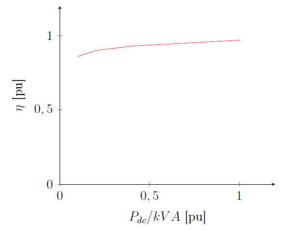
Figure 3: Inverter efficiency curve