Follow Mode
In the script below, a different loadshape has been used to drive the operation of the element. Figure 8 shows the evolution of the stored energy and the dispatch curve and Figure 9 shows the active power input and output at the storage grid interface.
!StorageOperationinFollowDispatchMode
Clear
New Circuit.Source bus1=Abase kv=0.48 phases=3 pu=1
New LoadShape.dispatch_shape interval=1 npts=24
~ mult=[0,1.0,1.0,1.0,0.5,0.5,0,0,0,0,0,0,0,0,0.5,0.75,1.0,1.0,1.0,1.0,0.75,0.5,0,0]
!Inverter Efficiency Curve
New XYCurve.Eff npts=4 xarray=[.1 .2 .4 1.0] yarray=[.86 .9 .93 .97]
New Storage.Storage1 phases=3 bus1=A kv=0.48 pf=1 kWrated=50 %reserve=20
~ effcurve=Eff kWhrated=500 %stored=50 state=idling
~ dispmode=follow model=1 daily=dispatch_shape
New Monitor.MonStorage1State element=Storage.Storage1 mode=3
New Monitor.MonStorage1Powers element=Storage.Storage1 mode=1 ppolar=No
Set voltagebases=[0.48]
Calcvoltagebases
Set mode=DailySolve
Plot Monitor object=MonStorage1State channels=(34)
Plot Monitor object=MonStorage1Powers channels=(135)
Note that a negative dispatch value means power flowing into the storage, i.e., charging state, and a positive value means power flowing out of the storage, i.e., discharging state. Note also the similarity of the dispatch curve and the storage powers at the grid interface. As presented in section 6.2, in follow mode, the charge and discharge rates are determined as a product of the dispatch curve value and the storage rated power, kWRated. For instance, at 3am, the multiplier is -1, so the storage charges at its rated power, 50 kW . At 3pm, a mutiplier of 0.5 leads the element to discharge at 25 kW.
To force the element to go to idling state, just specify a multiplier equal to 0. Finally, it is worth mentioning again that the storage operation will follow the dispatch curve only if there is still enough energy capacity left. For instance, at 10pm, the multiplier would lead the storage to discharge at 25 kW . However, at this time step, kWhstored has already reached the reserve value (100 kW), so the element goes to idling state.
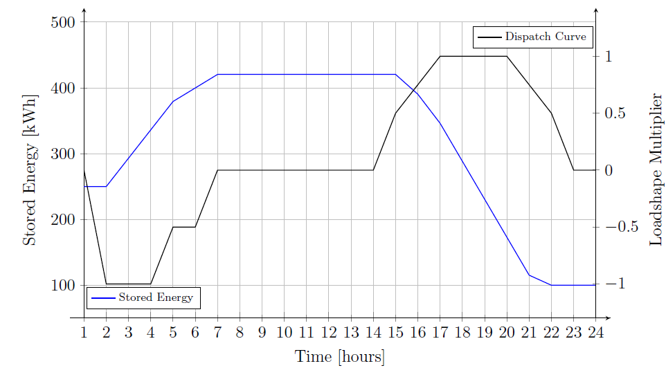
Figure 8. Stored Energy and Dispatch Curve

Figure 9. Powers at Storage Interface